3.5.5 Zone division system
General
It is recommended to ensure the zone division is working properly every month.
Zone division system
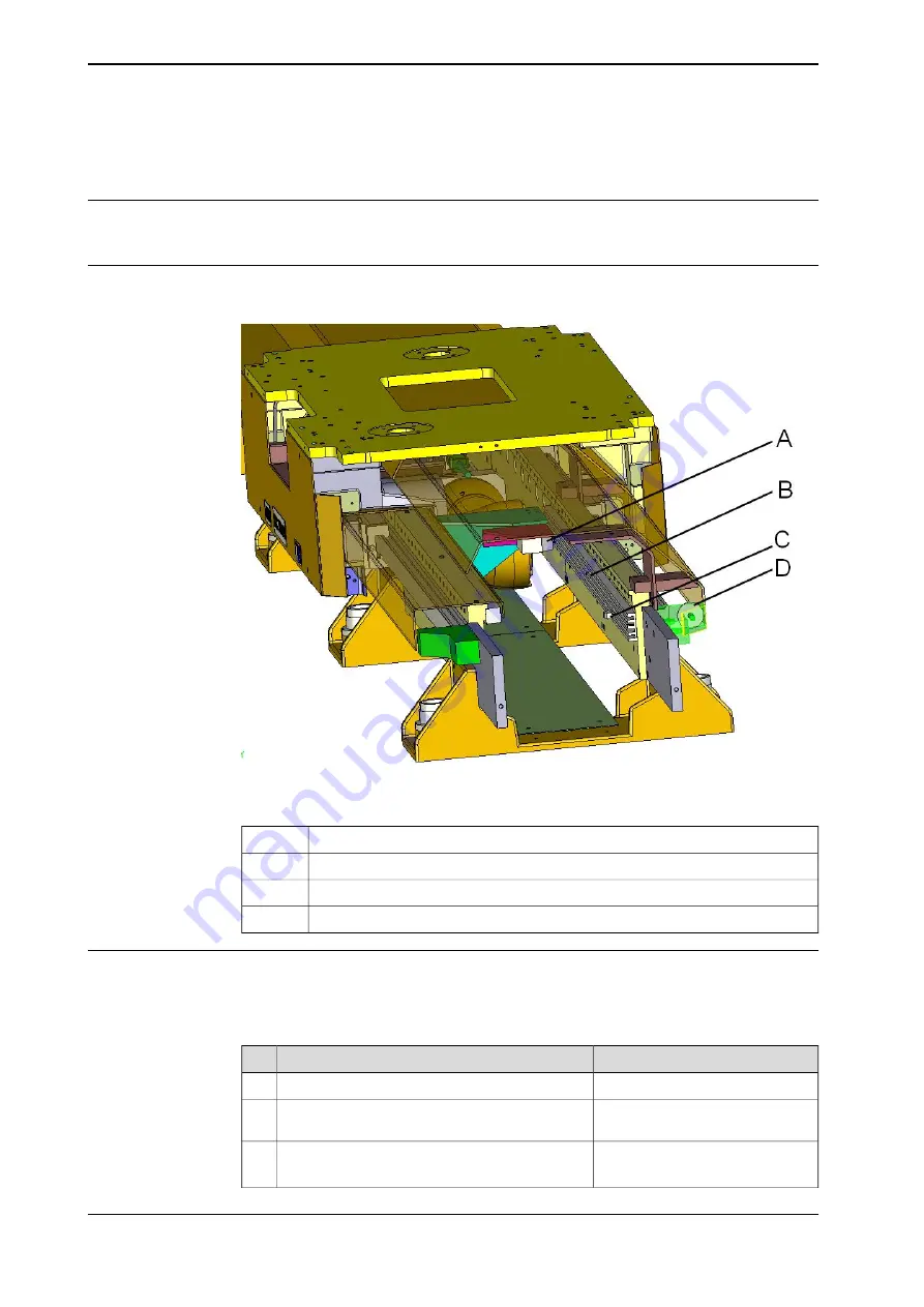
The figure below shows the location of the position switch:
xx1800001989
Inspect monthly the following parts:
Limit switch
A
Cam guide (on both ends of the FlexTrack)
B
Cam (on both ends of the FlexTrack)
C
Hard stop (bumper) (on both ends of the FlexTrack)
D
Verification of the effectiveness of the zone division sensor
If a 1 position, 2 position or 4 position limit switch is used to divide the track into
zones, then the following procedure should be followed to ensure it is functioning
correctly:
Note/Illustration
Action
Power off the IRC5 and activate the E-Stop.
1
Activate the limit switch sensor using an adhesive
tape.
2
Reset the E-Stop button and power on the
3
IRC5 in manual mode.
Continues on next page
136
Product manual - FlexTrack IRT501-66/66R/90/90R
3HAW050008590-001 Revision: C
© Copyright 20042018 ABB. All rights reserved.
3 Maintenance
3.5.5 Zone division system
Summary of Contents for FlexTrack IRT501 Series
Page 1: ...ROBOTICS Product manual FlexTrack IRT501 66 66R 90 90R ...
Page 8: ...This page is intentionally left blank ...
Page 38: ...This page is intentionally left blank ...
Page 118: ...This page is intentionally left blank ...
Page 174: ...This page is intentionally left blank ...
Page 178: ...This page is intentionally left blank ...
Page 182: ...This page is intentionally left blank ...
Page 186: ...This page is intentionally left blank ...
Page 198: ...This page is intentionally left blank ...
Page 200: ...This page is intentionally left blank ...
Page 202: ......
Page 203: ......


