While every effort has been taken to ensure the accuracy of information contained in this book and any associated promotional and information material
JOKAB SAFETY cannot accept responsibility for errors or omissions and reserves the right to make any improvements without notice. It is the users
responsibility to ensure that this equipment is correctly designed, specified, installed, cared for and operated to meet all applicable local, national and
international codes/regulations. Technical data in our book is correct to the level of accuracy of Jokab Safety´s test procedures as verified by various
international approved bodies. Other information (such as application examples, wiring diagrams, operation or use) is intended solely to illustrate the
various uses of our products. JOKAB SAFETY does not quarantee or imply that the product when used in accordance with such examples in a parti-
cular environment will fulfil any particular safety requirement and does not assume any responsibility or liability for actual use of the product based on
the examples given.
2TLC172243M9801, rev A
ABB AB/Jokab Safety
Varlabergsvägen 11
S-434 39 Kungsbacka
Sverige
ABB AB/Jokab Safety
Boplatsgatan 3
S-213 76 Malmö
Sverige
ABB AB/Jokab Safety
Mekanikervägen 6
S-564 35 Bankeryd
Sverige
ABB AB/Jokab Safety
Kanalvägen 17
S-183 30 Täby
Sverige
ABB AB/Jokab Safety
Fältmätargatan 16
S-721 35 Västerås
Sverige
Technical data
Manufacturer
Address
ABB AB / JOKAB SAFETY
Varlabergsvägen 11
SE-434 39 Kungsbacka
Sweden
Article number /
ordering data
Fox21:
2TLJ020160R2100
Fox22:
2TLJ020160R2200
Fox31:
2TLJ020160R0100
Fox32:
2TLJ020160R0200
Power supply
Rated insulating voltage
Ui
690V
Switching capacity AC-15
220.. 240V, 6A
380…440V, 4A
500V, 3A
Connection cable cross
sections single resp.
multi-strand
1-4 mm
2
Fine wire with core end
bush
(DIN 46228)
0.75-2.5 mm
2
Terminal screws
M4
Short circuit protection,
fusible cut-out (gL)
25A max.
Insulation requirements
met up to
480V~
Cable entry
M20
General
Protection class
IP65
Ambient temperature
Operation: -
15…+60
°C
Material:
Safety cover
Pedal
Aluminium
Shockproof thermoplastic
Size
See drawing
Weight (approx..) with
safety cover
Fox31: 1.7 kg
Fox32: 3 kg
Colour
Yellow and black
Mechanical life
Number of operations
Position 2: 1x10
6
Position 3: 3 x 10
5
Safety / Harmonized Standards
Conformity
European Machinery Directive 2006/42/EC
EN ISO 12100:2010,
EN 60204-1:2006+A1:2009,
EN ISO 13849-1:2008,
EN 60947-5-1:2003+A1:2009
EN ISO 13849-1
Performance level: Up to PL c, category 1
B
10d
: 300 000
Certificates
BG
EC Declaration of conformity
Dimensions
Fox21/31
Fox32/22
Original instructions
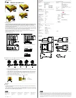
Fox
–
Safety foot operated switch
General description
The foot-operated safety switch Fox have been developed for industrial application with high mechanical and electrical
endurance. The foot-operated switches are used on wood processing machines, CNC machines, building machines and
bending machines. Normally a safety foot operated switch is used when the operator has to have both hands free.
Fox is available with a three or two positioning function in single and double pedal variants. Fox is always supplied with
duplicated contacts and robust safety cover.
Fox 31/32, three position function,
provide stop signals in the top and bottom position. Start/ready signals for separate
starting are provided in a distinct middle position. After a stop in the bottom position a start or clear signal cannot be given
before the reset knob has been operated and the pedal has been pushed into its middle position.
Fox 21/22, two-position function
, provide stop signal in the top or pedal released position. A start/ready signal for
separate starting is given in the bottom or fully depressed position.
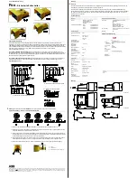
Connection example
–
Fox
Warning!
All the safety functions
must
be tested before starting up the system.
System description
–
three position pedal Fox 31/32
1) Normal: In resting position, the machine is OFF and the operator is preparing the work piece.
2) Operation: By pressing the pedal to the middle position the contacts 23-24 and 43-44 are closed and the safety
relay is activated. The machine is running.
3) E-Stop: If danger occurs the operator press the pedal to the third (bottom) position. A stop signal is immediately
sent to the machine. The safety relay falls and the machine stops. NB! Only available on Fox 31 and Fox 32.
4) Reset: After reaching the third position the pedal is locked and must be reset by turning the knob 90° counter
clockwise by hand, thereby releasing the latch.
5) Normal: The pedal is now in its stand-by position again, ready for next operation.
Maintenance
Warning!
The safety functions and the mechanics shall be tested regularly, at least once every year to confirm that all the safety
functions are working properly.
In case of breakdown or damage to the product, contact the nearest ABB/Jokab Safety Service Office or reseller. Do not
try to repair the product yourself since it may accidentally cause permanent damage to the product, impairing the safety of
the device which in turn could lead to serious injury to personnel.
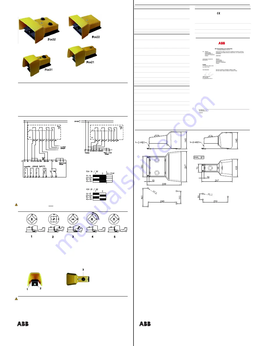
B) Pedal Fox21 with safety module RT9
A) Pedal Fox31 with safety module RT6
Version contact configuration:
1) Pedal
2) Contact point
3) Lockout reset knob


