Commissioning
Product manual
2CKA000073B5466
│
31
6.4 Links
Configuring, positioning and linking of the devices is carried out via
menu "Devices, scenes and groups".
Sensors and dimming actuators can be linked with each other. This allows simple On/Off
circuits or two-way circuits to be implemented.
The link is made via the configuration mode in the building plan of the Web-based user interface
of the System Access Point.
1. Open the building plan
–
via menu "Devices, scenes and groups" on the main page
–
via the switch icon in the menu bar on the left side
–
from the list of functions, via the "Floor plan" button
6.4.1
Linking sensor and actuator
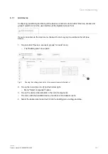
Configuring, positioning and linking of the devices is carried out via
menu "Devices, scenes and groups".
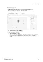
Fig. 16: Linking sensor and actuator (example illustration)
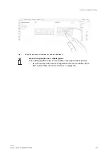
1. Select the sensor [1] in the building plan that is to be linked with the actuator (detailed
information is available in the system manual).
2. Select the actuator [2] that is to be switched by the sensor.
3. If necessary, make changes to the parameter settings.
4. Tap on "Save" to take over the settings.
–
A blue connecting line indicates the link between the two devices.
–
The selection can be cancelled via the "Deselect" button.
Notice
A sensor can be linked with several actuators.
A sensor can additionally be linked with scenes.

