Ex relevant specifications
D184B097U02
FV4000-VT4/VR4 / FS4000-ST4/SR4
105
Models designed for hazardous areas with American approval
Models
Approvals
VT43 / ST43 / VR43 / SR43 • Explosion-proof
XP/Class I/Div 1/BCD/T4 Ta = 70 °C Type 4X
• Dust-ignition-proof
DIP/Class II,III/Div 1/EFG/T4 Ta = 70 °C Type 4X
DIP/Class II,III /Div 2 /EFG /T4 Ta=70°C Type 4X
• Intrinsic
safety
IS/Class I, II,III/Div 1 ABCDEFG/T4 Ta = 70 °C Entity Type
4X
• Non-incendive
NI/Class I/Div 2/ABCD/T4 Ta = 70 °C Type 4X
11.1.2 Fieldbus devices
Models: VT4A, VR4A, ST4A, SR4A
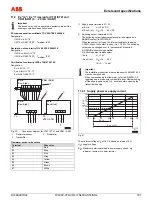
The hazardous area design of the device is based on the PTB's FISCO model (FISCO =
fieldbus intrinsically safe concept).
Proof of intrinsic safety for interconnection with other intrinsically safe equipment is not required
under the boundary conditions specified.
• All nodes must have FISCO approval, e.g., from the PTB, TÜV, BVS, KEMA.
• The maximum cable length in a segment is restricted to 1,000 m for EEx ia and 1,900 m for
EX ib.
• The bus cable (type A) has to exhibit the following values: R’ = 15
Ω
/km,
L’ = 0.4 ... 1 mH/km, C’ = 80 ... 200 nF/km
• The following applies for every field device (U
l
, I
l
, P
i
): U
0
≤
U
l
, I
0
≤
I
l
, P
0
≤
P
i
• All nodes act as passive current sinks.
• No power is fed in when a bus node is sending.
There is only one active device per segment (supply unit / segment coupler).
Designation: II 2G EEx ia IIC T4
Summary of Contents for FS4000-SR4
Page 125: ...Appendix D184B097U02 FV4000 VT4 VR4 FS4000 ST4 SR4 125 ...
Page 126: ...Appendix 126 FV4000 VT4 VR4 FS4000 ST4 SR4 D184B097U02 ...
Page 127: ...Appendix D184B097U02 FV4000 VT4 VR4 FS4000 ST4 SR4 127 ...
Page 128: ...Appendix 128 FV4000 VT4 VR4 FS4000 ST4 SR4 D184B097U02 ...
Page 129: ...Appendix D184B097U02 FV4000 VT4 VR4 FS4000 ST4 SR4 129 ...
Page 135: ......


