Ex relevant specifications
D184B097U02
FV4000-VT4/VR4 / FS4000-ST4/SR4
107
Change from one to two columns
11.2 Ex "ib" / Ex "n" design for VT41/ST41 and
VR41/SR41 (4 ... 20 mA / HART)
Important
The devices may only be operated in explosive areas if the
housing covers have been fully closed.
EC type-examination certificate TÜV 08 ATEX 554808 X
Designation:
II 2G Ex ib IIC T4
II 2D Ex tD A21 T85°C...Tmedium IP67
Declaration of conformity TÜV 08 ATEX 554833 X
Designation:
II 3G Ex nA [nL] IIC T4
II 3D Ex tD A22 T85°C...Tmedium IP67
Certificate of conformity IECEx TUN 07.0014 X
Designation:
Ex ib IIC T4...T1
Ex nA [nL] IIC T4...T1
Ex tD A21 IP6X TX°C
G00668
1
2
3
U
U
m
m
+
+
+
+
81
82
83
84
85
86
86
87
42
42
41
41
32
32
31
31
VR41 / SR41
VT41 / ST41
Ex ib
Ex nA [nL]
Ex ib
Ex nA [nL]
Ex ib
Ex nA [nL]
PA
1)
1)
=6
0V
=6
0V
2)
2)
PA
PA
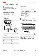
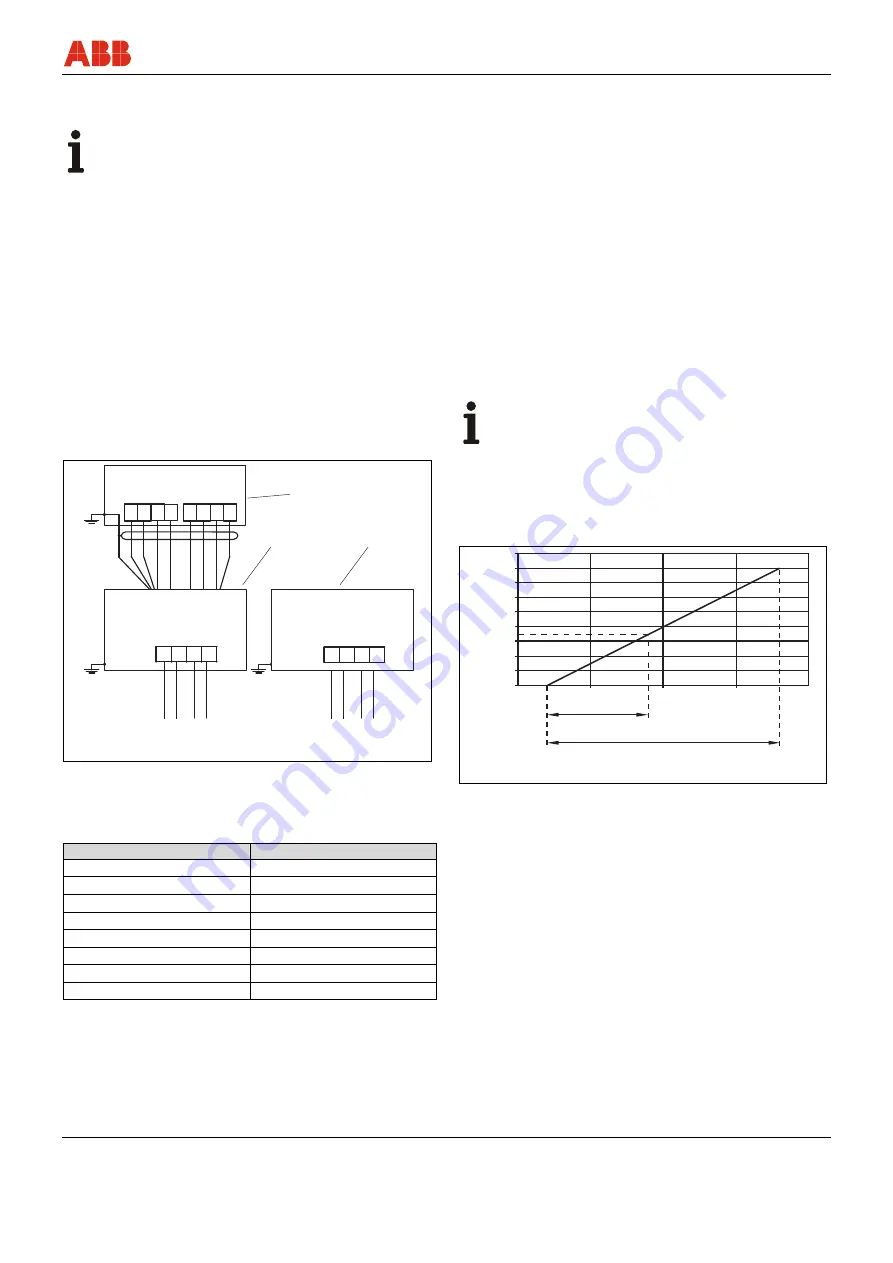
Fig. 50:
Connection diagram for VT41 / ST41 and VR41 / SR41
1
Flowmeter sensor
2
Transmitter
3
Flowmeter
Flowmeter sensor wire colors
Terminal
Wire color
81 Red
82 Blue
83 Pink
84 Gray
85 Yellow
86 Green
86 Brown
87 White
1) Supply power terminals 31 / 32
a) Ex ib:
Ui
= 28 V DC
b) Ex nA [nL] UB
= 14 … 46 V DC
2) Switching output, terminals 41/ 42
The switching output (passive) optocoupler is designed as a
NAMUR contact (to DIN 19234).
When the contact is closed, the internal resistance is approx.
1,000
Ω
. When the contact is open, it is > 10 K
Ω
. The switching
output can be changed over to "optocoupler" if required.
a) NAMUR with switching amplifier
b) Switching output (optocoupler)
- Ex ib:
Ui
= 15 V
- Ex nA [nL]:
UB
= 16 … 30 V
IB
= 2 … 15 mA
Important
The installation instructions in accordance with EN 60079-14
must be complied with.
When commissioning the flowmeter, refer to EN 50281-1-2
regarding use in areas with combustible dust. After switching
off the supply power, wait t > 2 minutes before opening the
transmitter housing.
11.2.1 Supply power or supply current
G00670
1,8
1,6
1,4
1,2
1
0
10
14
28
48
20
30
Ex ib
Ex nA [nL]
40
50
U
S
[V]
0,8
0,6
0,4
0,2
B
R[
K
]
Ω
Fig. 51
The minimum voltage US
of 14 V is based on a load of 0
Ω
.
US
= supply voltage
RB
= Maximum permissible load in power supply circuit, e.g.,
indicator, recorder or power resistor
Summary of Contents for FS4000-SR4
Page 125: ...Appendix D184B097U02 FV4000 VT4 VR4 FS4000 ST4 SR4 125 ...
Page 126: ...Appendix 126 FV4000 VT4 VR4 FS4000 ST4 SR4 D184B097U02 ...
Page 127: ...Appendix D184B097U02 FV4000 VT4 VR4 FS4000 ST4 SR4 127 ...
Page 128: ...Appendix 128 FV4000 VT4 VR4 FS4000 ST4 SR4 D184B097U02 ...
Page 129: ...Appendix D184B097U02 FV4000 VT4 VR4 FS4000 ST4 SR4 129 ...
Page 135: ......


