Specifications
122
FV4000-VT4/VR4 / FS4000-ST4/SR4
D184B097U02
12.11 Transmitter
Change from one to two columns
12.11.1 General specifications
G00633
C/CE
Step
Data/ENTER
Data/Enter
Step
C/CE
1
2
3
Fig. 66:
Transmitter keypad and display
1
Magnet sensors
2
Buttons for direct entry
3
Can be r/- 90 °
Measuring ranges
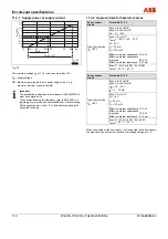
The full-scale value can be set at any point between the maximum
possible upper range value 1.15 x QmaxDN and 0.15 x QmaxDN.
Parameter setting
Data can be entered using 3 buttons (not on the Ex "d" hazardous
area design) or, if the housing is sealed, directly externally using a
magnet stick.
Data is entered in plain text with the display or using digital
communication via the HART protocol or PROFIBUS
PA/FOUNDATION Fieldbus.
Flow operating modes
The following operating modes can be selected dependent upon the
design purchased (with or without Pt100):
Fluid medium:
• Operating
flow
•
Mass flow with constant or temperature-dependent density
Gas/steam medium:
• Operating
flow
•
Mass flow with constant or temperature-dependent density (at
constant pressure)
•
Standard flow with constant or temperature-dependent standard
factor (at constant pressure)
•
Mass flow with saturated steam and temperature-driven density
Data backup
Counter readings and parameters for specific measuring points
backed up in FRAM (more than 10 years without supply power) in the
case of shutdown or should the supply voltage fail.
Important
The flowmeter corresponds to NAMUR recommendations NE21.
Electromagnetic compatibility of equipment for process and lab
control technology 5/93 and EMC Directive 89/336/EEC (EN 50081-
1, EN 50082-2). Note: EMC protection and protection against
accidental contact are limited when the housing cover is open.
Damping
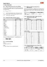
Configurable from 1 ... 100 s, corresponds to 5
τ
.
Q
v min
(low flow)
Configurable between 0 ... 10 % of QmaxDN (max. operating flow per
nominal size). The actual low flow is determined by application and
installation.
Function tests
Software-internal function tests can be used to test individual internal
modules. For the purpose of commissioning and testing, the current
output (4 ... 20 mA design) or the digital output signal (fieldbus
designs) can be simulated in line with flowrates selected by the user
(manual process control). The switching output can also be controlled
directly for the purpose of function testing.
Electrical connection
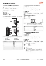
Screw-type terminals, plug-in connection on PROFIBUS PA (option)
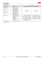
cable gland: -standard., Ex "ib" / Ex "ia": M20 x 1.5; NPT 1/2 ” -Ex d”:
NPT 1/2”
Degree of protection
IP 67 to EN 60529
Display
High contrast LCD, 2 x 8 digits (4 ... 20 mA design) or 4 x 16-digit
(PROFIBUS PA / FOUNDATION Fieldbus fieldbus design). Shows
the instantaneous flowrate along with the totalized flow or
temperature of the medium (option).
On the 4 ... 20 mA design, the multiplex function enables 2 values
(e.g., flowrate and totalized flow) to be displayed virtually in parallel.
Up to 4 values can be displayed on the fieldbus design.
Switching output terminals 41 / 42
(standard on all designs)
The function can be selected via the software:
-
Max./min. alarm for flow or temperature
- System
alarm
-
Pulse output: fmax: 100 Hz; ton: 1 ... 256 ms
Contact type:
-
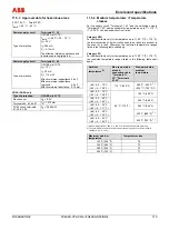
Standard and Ex "d": Optocoupler UH = 16 ... 30 V
IL = 2 ... 15 mA
-
Ex "ib" / Ex "ia": Configured as NAMUR contact
Summary of Contents for FV4000-VT4
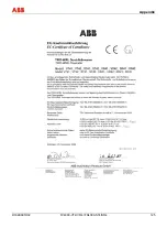
Page 125: ...Appendix D184B097U02 FV4000 VT4 VR4 FS4000 ST4 SR4 125 ...
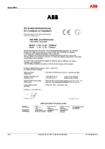
Page 126: ...Appendix 126 FV4000 VT4 VR4 FS4000 ST4 SR4 D184B097U02 ...
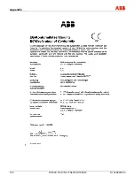
Page 127: ...Appendix D184B097U02 FV4000 VT4 VR4 FS4000 ST4 SR4 127 ...
Page 128: ...Appendix 128 FV4000 VT4 VR4 FS4000 ST4 SR4 D184B097U02 ...
Page 129: ...Appendix D184B097U02 FV4000 VT4 VR4 FS4000 ST4 SR4 129 ...
Page 135: ......


