background image


Page 148


© Copyright 2023 ABB. All rights reserved. 


Millennium SC_MAN 


Rev 2.0


T1.317 


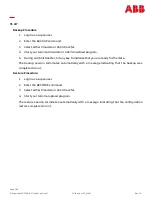
Backup Procedure


1.


Login as a super

-

user.


2.


Enter the BACKUP command.


3.


Select either Xmodem or ASCII transfer.


4.


Start your terminal Xmodem or ASCII download program. 


5.


During an ASCII transfer, hit any key to indicate that you are ready for the data.


The backup session terminates automatically with a message  indicating  that the  backup was 
completed or not. 


Restore Procedure:


1.


Login as a super

-

user.


2.


Enter the RESTORE command.


3.


Select either Xmodem or ASCII transfer.


4.


Start your terminal upload program.


The restore session terminates automatically with a message indicating that the configuration 
restore completed or not.


Summary of Contents for Galaxy Millennium J2011002

Page 1: ...Page 1 Copyright 2023 ABB All rights reserved Millennium SC_MAN Rev 2 0 PRODUCT MANUAL Galaxy Millennium SC Controller J2011002 Product Manual Ordering code 850015641 ...

Page 2: ...v 2 0 Notice The information specifications and procedures in this manual are subject to change without notice ABB assumes no responsibility for any errors that may appear in this document 2012 abbpowerconversion com All International Rights Reserved Printed in U S A ...

Page 3: ...6 Default Display 26 LCD 27 LEDs 27 Push Button Keys 28 Test Jacks 28 Serial PC Port 28 Alarm Buzzer 29 Contrast Adjust 29 Display Menus 30 Configuration Menus 30 Control and Operations Menus 32 History Menus 33 Statistics Menus 33 Status Menus 34 Installation 36 Preparation 36 Safety and Precautions 36 Installation Materials 36 Plan Rectifier Interface Cards First ID Settings 36 Plan Wiring Trans...

Page 4: ...ntrol Signals 131 Fuse Alarm Major FAJ BSL 63 134 Fuse Alarm Minor FAN BSL 65 134 Open String Alarm OS BSL 72 135 Aux Major AMJ BSL 64 135 Aux Minor AMN BSL 66 135 Low Voltage Disconnect Active LVD1 BSL 84 135 Low Voltage Disconnect Active LVD2 LVD2R BSL 61 62 135 External Boost Option TFLT TBST PBT BSL 67 69 135 Rectifier Hold OFF on Engine Option RO ROR BSL 77 78 135 Rectifier External Sequence ...

Page 5: ...acts 203 Product Warranty 203 Revision History 205 List of Figures Figure 1 MSC Chassis 11 Figure 2 MSC Controller Front 12 Figure 3 Controller Arrangements 13 Figure 4 BJC Card Slots 14 Figure 5 Front Panel 16 Figure 6 Controller Dimensions 20 Figure 7 Card Locations 21 Figure 8 MCR1B 2B Circuit Card 22 Figure 9 MSCB_FB Fuse Card 22 Figure 10 Backplane 23 Figure 11 Modem BSM6 23 Figure 12 Alarm T...

Page 6: ...ons 62 Figure 35 MCS Auxiliary Board CP2 64 Figure 36 MSC 75 Figure 37 Fuse Card 76 Figure 38 Cards Front 77 Figure 39 Cards Rear 77 Figure 40 Card Connections 78 Figure 41 RIC ID Setting 79 Figure 42 Modem Card Wiring 80 Figure 43 Remote Interface Module RIM Side B 81 Figure 44 Controller Connections Rear 82 Figure 45 Controller Connections Front 82 Figure 46 BSL4_MSC Alarm Terminations 84 Figure...

Page 7: ...Equalize S3 67 Table 20 Other Controller DIP Switch Settings 68 Table 21 Other Controller Alarm Threshold Settings 69 Table 22 Other Controller Plant Shunt Settings 69 Table 23 Other Controller Low Voltage Disconnect Settings 69 Table 24 Other Controller Slope Thermal Compensation Settings 70 Table 25 Other Controller Rectifier Float Setpoints 70 Table 26 MSC Interface Reference 83 Table 27 Therma...

Page 8: ...larm Input Objects and Attributes 170 Table 63 Data Switch Objects and Attributes 171 Table 64 Remote Peripheral Monitor Objects and Attributes 172 Table 65 Distribution Current Objects and Attributes 173 Table 66 Controller Analog Input Objects and Attributes 174 Table 67 Other Measurement Objects and Attributes 174 Table 68 Reporting Objects and Attributes 175 Table 69 Remote Communication Objec...

Page 9: ...Page 9 Copyright 2023 ABB All rights reserved Millennium SC_MAN Rev 2 0 This page is intentionally blank ...

Page 10: ... plants containing up to 72 GP serial rectifiers up to 16 serial converters up to 32 BICs and up to 16 parallel rectifiers A maximum combination of 90 GP nodes can be directly managed on the rectifier serial bus MSC performs many functions described more thoroughly in following sections Feature Summary Alarm Detection Identification and Reporting System and Component Status System and Feature Conf...

Page 11: ...f the MSC This eliminates the need to manage multiple cards for features as well as plant voltage Standard communications features now include remote 10 100 Base T network access to display power system operating status and available information via the world wide web internet or your enterprise network intranet using standard browsers Upgrading to the MSC is easy Software features include and exp...

Page 12: ... same rectifier cables as the Galaxy SC controller MSC can be supplied with an onboard M2 controller or utilize an M2 controller mounted in a GPS plant or in a relay rack The front panel provides a backlit LCD display with an easy to use push button and menu driven interface The panel can be used to operate and program basic functions and access real time date history statistics and measured value...

Page 13: ...Page 13 Copyright 2023 ABB All rights reserved Millennium SC_MAN Rev 2 0 Figure 3 Controller Arrangements1 1 MSC M2 MSC without M2 ...

Page 14: ... rights reserved Millennium SC_MAN Rev 2 0 MSC Controller With On Board M2 Figure 4 BJC Card Slots MSC has slots for 2 BJC Rectifier Interface cards for legacy parallel rectifiers BJC card slots Front View with Onboard M2 Controller ...

Page 15: ...troller Maximum of 90 serial switch mode rectifiers Supported rectifier families 570 595 596 NP CPS6000 QS AC and NE Maximum of 32 Bay Interface Cards BICs Maximum of 72 serial converters Maximum of 8 ringers Maximum of 6 LVD distribution cards Maximum of 8 VIM1s Alarms Standard and custom User Defined system alarms Alarm test Alarm cut off Multiple level alarm severity Critical Major Minor Warnin...

Page 16: ...e Mid string Voltage modules 3 voltages per module Up to 18 battery temperatures via optional 1 Wire QS873A modules On board external voltage channel On board 4 20mA transducer channel Maintenance Tools User Programmable Alarms History Statistics Diagnostics Derived Channels Inventory Management Configuration Backup Restore Memory Non Volatile Battery Backed Remote and Local Software Upgrade Front...

Page 17: ... to existing Galaxy SC 2 Connection to the Local Port disables modem communication Local Serial Access Local Port see Front Panel User Interface section above Ethernet Port Browser Interface standard and custom web pages for browsers HTTP Remote Access Integrated 10 100Base T Ethernet Network capability Supports TCP IP Version 5 SNMP Version 2c SMTP TL1 DHCP Telnet FTP Browser Interface standard a...

Page 18: ...ediction Supports a variety of batteries Use configurable Low Reserve Time Alarm Integrated At Rate Calculator for estimation purposes Battery Discharge Testing Manual Periodic Plant Battery Test PBT input driven Battery Discharge trace data Float Boost Mode Control Manual Timed Boost Locally T1 317 and remotely initiated External Timed Boost Battery Thermal Protect module Boost BTP Auto Boost ter...

Page 19: ...nputs 22 Inputs Engine signal inputs Battery test inputs External Float Boost control 2 User programmable Remote Peripheral Monitoring Integrated serial bus Maximum 300 meter serial bus 512 channels maximum Transducer interface Battery Shunt Voltage Temperature and Binary monitoring Control Relays Channels can be programmed for custom alarms 1 Wire Monitoring Integrated serial bus 6 ES771 Mid stri...

Page 20: ...nium SC_MAN Rev 2 0 Hardware Chassis MSC mounts in frames 19 23 and 25 inch See Figure 6 It is designed to be physically backwards compatible with existing Galaxy SC rear access controllers for field replacements or upgrades Figure 6 Controller Dimensions ...

Page 21: ...MAN Rev 2 0 Controller Cards Figure 7 Card Locations MSC without On Board M2 does not include MCR1B 2B Microprocessor Front Panel BSL Alarm Terminations BSM6 Modem Front View with Onboard M2 Controller Backplane Circuit Card Layout Card Locations With On Board M2 ...

Page 22: ...he MCR2B The MCR2B contains the main microprocessor with of Flash memory and RAM It also contains the hardware for the Ethernet control Factory calibration values for the analog circuits located on the MCR1B are stored in memory on the MCR2B Fuse Description Fuse Size F1 Controller Input Power 3A F2 Alarm Battery Supply ABS 1 3A Fuses Fuse Card MSCB_FB Figure 9 MSCB_FB Fuse Card Fuses for Controll...

Page 23: ...plane Each module is associated with the Rectifier Interface Card on the same side of the chassis RS 485 GP Serial Connections To Rectifiers To all GP devices except M2 To Controller To M2 For MSC without On Board M2 Backplane Connections RS 485 GP Serial Connection Modem Option BSM6 Figure 11 Modem BSM6 Optional BSM6 Modem card provides dial up access at 33 6k bps ...

Page 24: ...lock standard BSL4_MSC Wire wrap block option Rectifier Interface Cards RIC BJC1_MSC and BJC2_MSC Figure 13 Rectifier Interface Card One or two of these cards will always be present in the MSC BJC1_MSC Control 8 ABB Ferros BJC2_MSC Control 8 ECS Rectifiers OR 8 third party parallel rectifiers MSC can control a total of up to 16 parallel rectifiers Remote Interface Modules are also required See Tab...

Page 25: ...of the chassis See Table 40 Rectifier Cables J2011002 Remote Interface Modules RIM up to 8 rectifiers each 108028671 J85501F1L31 ABB Ferros without enhanced communications 108028697 J85501F1L32 ABB Ferros with enhanced communications 108208689 J85501F1L34 Third party parallel Ferro SCR rectifiers 108572660 J85501F1L35 ABB ECS 364 Rectifiers Supporting Documents Table 3 Supporting Documents Name Nu...

Page 26: ...proximately every two seconds The front panel display offers a series of menus that allow the user to Configure Control View Status View History View Statistics Perform Diagnostics These menu operations are accomplished by navigating through different screens of Alarms of Warnings Date Time Plant Voltage Plant Load Current An Hourglass may appear in the lower left hand corner of the screen This in...

Page 27: ...ls Figure 16 Front Panel LEDs Depending on the LCD option utilized the LCD assemblies contain two rows of LEDs at the right side of the interface card or two columns of LEDs at the left side of the interface card as seen in Figure 16 The segregated sections of LEDs provide an indication of the alarm source rectifier battery distribution communication controller remote modules and the severity Crit...

Page 28: ...lay to allow easy connection to a personal computer or terminal using ANSI T1 317 object oriented command language ABB s EasyView is also available to provide a user friendly system interface locally or remotely See Figure 16 Table 4 Push Button Key Functionality Key Function Up arrow Use to navigate the menu press the key to move the cursor up one line Down arrow Use to navigate the menu press th...

Page 29: ...s located on the front panel display assembly It can be programmed from the front panel display to operate as follows Contrast Adjust Press the or key to change the display contrast Repeat or hold the button until the desired contrast is reached Disabled for ALL Alarms Audible on PCR Audible on PMJ Audible on PMN ...

Page 30: ...Page 30 Copyright 2023 ABB All rights reserved Millennium SC_MAN Rev 2 0 Display Menus Configuration Menus Figure 17 Configuration Menus 1 of 2 ...

Page 31: ...Page 31 Copyright 2023 ABB All rights reserved Millennium SC_MAN Rev 2 0 Figure 18 Configuration Menus 2 of 2 ...

Page 32: ...Page 32 Copyright 2023 ABB All rights reserved Millennium SC_MAN Rev 2 0 Control and Operations Menus Figure 19 Control and Operations Menus ...

Page 33: ...Page 33 Copyright 2023 ABB All rights reserved Millennium SC_MAN Rev 2 0 History Menus Figure 20 History Menus Statistics Menus Figure 21 Statistics Menus ...

Page 34: ...Page 34 Copyright 2023 ABB All rights reserved Millennium SC_MAN Rev 2 0 Status Menus Figure 22 Status Menus 1 of 2 ...

Page 35: ...Page 35 Copyright 2023 ABB All rights reserved Millennium SC_MAN Rev 2 0 Figure 23 Status Menus 2 of 2 ...

Page 36: ...procedure Be aware of the presence of unfused battery potential in the vicinity of the controller Use only insulated tools Make sure the system is properly grounded per the National Electrical Code and local building codes Remove all metal jewelry before beginning the installation Observe ESD protection while installing circuit cards Wear grounded antistatic wrist straps when handling all circuit ...

Page 37: ...or 10 to the rotary switch setting 1 is the lowest valid rectifier ID 0 is an invalid rectifier ID Single BJC Type Systems Plants with only ABB AT T type rectifiers or with only non ABB AT T type rectifiers will use a single type of BJCs either all BJC1_MSCs or all BJC2_MSCs In this case set BJC First Rectifier IDs so that they are consecutive Example 12 rectifiers are numbered 1 through 12 First ...

Page 38: ...umper 0 Positions 1 through 7 connect to ABB AT T rectifiers 4 through 10 Position 8 is available for future use Step Action to Plan Rectifier Interface Cards First ID Settings 1 The First ID Setting for the Side A Rectifier Interface Card is the lowest rectifier number of existing rectifiers This card type must match the rectifier type see above Write it in Table 5 below 2 Are all BJC cards of th...

Page 39: ...d BSL Pins Table 36 Alarm Descriptions BLS Pins and Signal Names Table 37 Alarm and Control Inputs Descriptions BLS Pins and Signal Names Alarm and Control Signals section 3 Rectifier Wiring Fill in Table 41 Commercial Rectifier Wiring H285 226 G62 Use the following to determine rectifier cable wiring the existing rectifier documentation the existing controller documentation plant documentation Pl...

Page 40: ...file saved in step 1 for reference b Open the backup file in text editor such as Notepad not in Word c At the start of the file insert lines to ADD each Ferro rectifier that will be present in the system For each rectifier the line will be ADD Gxx where xx is the rectifier number d Remove the battery type definitions incompatible with the MSC Delete all lines starting with CHA BTxx where xx is 01 ...

Page 41: ...s Place any battery load contactors in an independent safe state Disconnect Rectifier Control Cables Adjust Rectifiers back to Float Voltage Power Down the controller Remove the controller Proceed to the appropriate Controller Removal Section Galaxy SC Controller Removal MCS Controller Removal Other Controller Removal NOTE This procedure will cause the office alarms to operate Inform the operating...

Page 42: ...ights reserved Millennium SC_MAN Rev 2 0 Galaxy SC Controller Removal This section provides a method for preparing a Galaxy SC rear access controller for removal Figure 25 Galaxy SC Controller Front Figure 26 Galaxy SC Controller Rear ...

Page 43: ... are on and sharing load 4 Record the DIP Switch Settings DIP Switch settings determine if some controller features are enabled or disabled If the MSC controller is to have the same configurations the settings on the Galaxy SC controller SW201 SW202 SW203 and SW204 must be recorded All of these DIP switches except SW201 2 auxiliary portRS 232 485 work in coordination with software settings Galaxy ...

Page 44: ...word Reset for Indep Modem Table 8 Galaxy SC Intelligent Controller BJH DIP Switch Settings Switch Position Description Switch Setting 1 or 0 Closed 1 Enabled SW203 8 Remote rectifier in standby SW203 7 Remote rectifier turn on SW203 6 Full access through local port4 SW203 5 Full access through auxiliary port SW203 4 Full access through modem port SW203 3 Configure via Modem aux local port SW203 2...

Page 45: ...e front panel display MENU CONFIG ALARM THRESHOLDS 6 Plant Shunt Settings Record shunt information so that it can be programmed when the new controller has been installed Record this information by selecting the following menus from the front panel display MENU CONFIG PLANT Table 9 Galaxy SC Alarm Threshold Settings Alarm Float Boost optional High Voltage High Float Voltage Battery on Discharge Re...

Page 46: ...ompensation Settings Record slope thermal compensation information if implemented in the system so that it can be programmed when the new controller has been installed Record this information by selecting the following menus from the front panel display MENU CONFIG STC Table 11 Galaxy SC Low Voltage Disconnects Settings Contactor 1 Type Disconnect Volt Reconnect Volt Contactor 2 Type Disconnect Vo...

Page 47: ... Battery and Load contactors if present in the system so that they do not OPEN during the controller replacement To ensure that these contactors do not open force all LVLD and LVBD contactors closed NOTE These contactors may have already been forced closed per customer requirements If so then proceed to the next step To force LVLD contactors closed place SW300 in the up position as shown in Figure...

Page 48: ...N Rev 2 0 Step Action to Prepare the SC Controller for Removal Figure 28 LVBD Contactor Control BJN Card SW300 Contactor Type Control Card and Switch To Force Closed Change to Load EBV SW300 UP Battery BJN SW300 UP for height cabinets Down for full height cabinets ...

Page 49: ...0 90 0 0 0 0 0 1 1 1 1 1 0 0 0 0 0 0 0 0 0 0 0 0 0 1 1 1 1 1 0 0 0 0 1 0 1 0 1 1 1 0 52 00 10 20 30 40 0 0 0 0 0 1 1 1 1 1 0 0 0 0 0 0 0 0 1 1 1 1 1 0 0 1 1 1 0 0 0 0 1 0 1 01 1 1 1 0 52 50 60 70 80 90 0 0 0 0 0 1 1 1 1 1 0 0 0 0 0 1 1 1 1 1 0 0 0 1 1 1 1 1 0 0 0 1 1 0 1 0 0 1 1 0 53 00 10 20 30 40 0 0 0 0 0 1 1 1 1 1 0 0 0 1 1 1 1 1 0 0 1 1 1 0 0 1 1 1 0 0 0 1 1 0 1 0 0 1 1 0 53 50 60 default 70 ...

Page 50: ...0 0 0 0 0 1 1 1 1 1 0 0 1 1 1 1 1 0 0 0 0 1 0 1 1 1 0 0 0 1 57 00 10 20 30 40 1 1 1 1 1 0 0 0 0 0 0 0 0 1 1 1 1 0 0 0 1 1 0 0 0 1 1 0 0 0 0 1 0 1 1 1 1 0 0 1 57 50 60 70 80 90 1 1 1 1 1 0 0 0 0 0 1 1 1 1 1 0 0 0 0 0 0 0 1 1 1 1 1 0 0 1 0 1 0 1 0 1 1 0 0 0 58 00 10 20 30 40 1 1 1 1 1 0 0 0 0 0 1 1 1 1 1 0 0 1 1 1 1 1 0 0 0 1 1 0 0 1 0 1 0 1 0 1 1 0 0 0 58 50 60 70 80 90 1 1 1 1 1 0 0 0 0 0 1 1 1 1 ...

Page 51: ...0 0 0 0 0 0 0 0 1 1 1 1 1 1 1 1 1 1 0 0 0 1 1 1 1 1 0 0 0 0 1 0 1 0 1 1 1 0 25 75 80 85 90 95 0 0 0 0 0 0 0 0 1 1 1 1 1 0 0 1 1 1 0 0 1 1 1 0 0 1 1 1 0 0 0 0 1 0 1 0 1 1 1 0 26 00 05 10 15 20 0 0 0 0 0 1 1 1 1 1 0 0 0 0 0 0 0 0 0 0 0 0 0 1 1 1 1 1 0 0 0 0 1 0 1 0 1 1 1 0 26 25 30 35 40 45 0 0 0 0 0 1 1 1 1 1 0 0 0 0 0 0 0 0 1 1 1 1 1 0 0 1 1 1 0 0 0 1 1 0 1 0 0 1 1 0 26 50 55 60 65 70 0 0 0 0 0 1 ...

Page 52: ... 0 0 1 1 1 1 1 0 0 0 1 1 0 1 0 0 1 1 1 28 25 30 35 40 45 1 1 1 1 1 0 0 0 0 0 0 0 0 0 0 0 0 0 1 1 1 1 1 0 0 1 1 1 0 0 0 1 1 0 1 0 0 1 1 1 28 50 55 60 65 70 1 1 1 1 1 0 0 0 0 0 0 0 0 0 0 1 1 1 1 1 0 0 0 1 1 1 1 1 0 0 0 1 1 1 1 0 0 1 1 1 28 75 80 85 90 95 1 1 1 1 1 0 0 0 0 0 0 0 1 1 1 1 1 0 0 0 1 1 0 0 0 1 1 0 0 0 0 1 0 0 1 0 0 0 1 1 29 00 05 10 15 20 1 1 1 1 1 0 0 0 0 0 1 1 1 1 1 0 0 0 0 0 0 0 1 1 1...

Page 53: ... 1 0 0 0 0 1 0 0 1 1 0 0 1 1 30 25 30 35 40 45 1 1 1 1 1 1 1 1 1 1 0 0 0 0 0 0 0 1 1 1 1 1 0 0 0 1 1 0 0 0 0 1 0 0 1 1 0 0 1 1 30 50 55 60 65 70 1 1 1 1 1 1 1 1 1 1 0 0 0 0 0 1 1 1 1 1 0 0 1 0 1 1 1 0 0 0 0 1 0 1 1 1 0 0 0 1 30 75 80 85 90 95 1 1 1 1 1 1 1 1 1 1 0 0 1 1 1 1 1 0 0 0 1 1 0 0 0 1 1 0 0 0 0 1 0 0 1 1 0 0 1 1 31 00 05 10 15 1 1 1 1 1 1 1 1 1 1 1 1 0 0 0 0 0 0 1 1 1 1 0 0 0 1 0 0 1 0 0 ...

Page 54: ...The rectifier will switch to internal regulation ABB rectifiers automatically switch to internal regulation Non ABB rectifiers must be manually configured for internal regulation Consult the rectifier manual for method of configuration for internal regulation The system voltage will increase NOTE This requires a readjustment of the rectifier output volts adjust potentiometer as detailed in the fol...

Page 55: ...ciated rectifier regulation fuse A1 to A8 B1 to B8 and C1 to C8 from the BJF Termination Fuse Board Figure 29 Galaxy SC Rectifier Fuses 7 Turn the rectifier Power switch ON 8 Adjust the rectifier output voltage potentiometer to obtain the same current observed in Step 1 readjustment 9 Are all rectifiers operating on local sense Yes 1 Verify that the system charge bus is within tolerance 2 Make fin...

Page 56: ...rom Galaxy SC The serial rectifier interface cable is terminated RJ 45 connector to the J85501F 1 L 36 serial rectifier interface module mounted to backplane on the rear of the Galaxy SC controller 1 Mark Tag Disconnect and Insulate the serial rectifier interface cable Step Action to Remove Modem Connections Is there a phone cable attached to the Modem Port Interface Card installed on the rear of ...

Page 57: ...alaxy SC TB2 and TB3 NOTE STOP Before proceeding with this step verify that ABS supply pins 30 31 46 and 47 is not connected to anything If there are connections to ABS perform proper transitioning procedures and move these connections to another source 1 Mark Tag Remove and Insulate all connections terminating on TB2 and TB3 You may need to reference a controller product manual for labeling the c...

Page 58: ... cables Make sure that office records are present Refer to Table 79 Galaxy SC Wiring Plan Cross Reference and the Galaxy SC Product Manual Step Action to Power Down Galaxy SC Controller Power Down Figure 31 Galaxy SC TB1 Plant Connections Figure 32 Galaxy SC Controller Fuses 1 Remove all 8 controller fuses using a fuse puller see Figure 32 Galaxy SC Controller Fuses 2 Mark Tag Insulate and Remove ...

Page 59: ...hassis 3 Cut all remaining tie straps that inhibit removal of the MCS controller 4 Fully insulate the area around the MCS using a flameproof matting or equivalent Make sure that these are insulated Bus bars Battery leads Ground leads 5 Remove all 6 nuts 3 on left side and 3 on right side using a 6 32 hex nut driver Slide the Galaxy SC out of the bay using a second person for support CAUTION Use tw...

Page 60: ... 2 Operate all alarms to be sure all alarms are operating properly For example put a wire jumper between the terminal block 1 terminal 1 and 2 Figure 33 MCS Alarm Circuit 3 Open the door of the MCS controller by pulling down on the top side 4 Record older vintages of feeder drain or universal shunt monitoring boards The configuration will be lost when the controller is powered down 5 Locate the ED...

Page 61: ...ect external voltage sense leads at the rectifier Leave the wires in place for later reconnection 5 Convert the rectifier to internal sense Consult the rectifier manual for details 6 Remove the associated rectifier regulation fuse F1 to F16 from the controller 7 Remove the rectifier control cable from the controller backplane 8 Turn the rectifier Power Switch ON 9 Adjust the rectifier output volta...

Page 62: ...Page 62 Copyright 2023 ABB All rights reserved Millennium SC_MAN Rev 2 0 Disconnect Other MCS Connections Figure 34 MCS TB1 Alarm Connections ...

Page 63: ...1 Alarm Connections Disconnecting will prevent continuous office alarms during controller transition For example twist together wires from positions 39 and 40 PMJV and PMJVR 5 Remove Mark And Insulate all external wires office alarms terminated on TB1 6 Cut the existing MCS alarm connections at TB1 on the MCS controller Leave adequate length for reconnection to MSC Alarm connections on MSC do not ...

Page 64: ...switches S1 S2 and S3 2 Yes Proceed No Nothing to record Proceed to Remove the MCS Controller 3 Record the setting values of DIP switches S1 S2 and S3 in Table 16 Float BD L2 setting from S1 HV float shutdown settings from S2 HV equalize settings from S3 Table 16 MCS DIP Switch Settings DIP Switch Default Use Table Threshold Value S1 BD 51 25 25 50 Table 17 Battery on Discharge S2 HV 53 00 26 00 T...

Page 65: ... 70 55 10 52 10 O O O X O 28 70 27 20 54 60 51 60 X O O X O 28 60 27 10 54 50 51 50 O X O X O 28 10 26 60 54 00 51 00 X X O X O 28 50 27 00 54 50 51 50 O O X X O 28 00 26 50 54 90 51 90 X O X X O 27 90 26 40 54 00 51 00 O X X X O 27 40 25 90 53 40 50 40 X X X X O 28 20 26 70 54 00 51 00 O O O O X 27 70 26 20 53 60 50 80 X O O O X 27 60 26 10 53 50 50 50 O X O O X 27 10 25 80 53 00 50 00 X X O O X ...

Page 66: ...lts S2 1 S2 2 S2 3 S2 4 57 00 O O O O 56 50 X O O O 56 50 O X O O 29 80 56 00 X X O O 29 75 56 00 O O X O 29 30 55 50 X O X O 29 25 55 50 O X X O 28 80 55 00 X X X O 28 75 55 00 O O O X 28 30 54 50 X O O X 28 25 54 50 O X O X 27 80 54 00 X X O X 27 75 54 00 O O X X 27 30 53 50 X O X X 27 25 53 50 O X X X 26 75 53 00 X X X X 5 Switch S2 5 will be open for 48 volt system and closed for a 24 volt sys...

Page 67: ... 55 50 O X X X 29 75 55 00 X X X X 6 Switch S3 5 will be open for 48 volt system and closed for a 24 volt system Remove the MCS Controller Step Action to Remove the MCS Controller 1 Cut all remaining tie straps that inhibit removal of the MCS controller 2 Fully insulate the area around the MCS using a flameproof matting or equivalent Make sure that these are insulated Bus bars Battery leads Ground...

Page 68: ...e Alarm center has been notified of potential alarms being generated 1 Place System in Float Mode From the Default Display of the controller note the system mode of operation If the mode is FLOAT go to Step 2 If the mode is something other than Float ex BOOST place the system in FLOAT mode before going to Step 2 2 Turn all Available Rectifiers On If rectifiers have been manually turned off turn th...

Page 69: ...r being replaced for Low Voltage Disconnects Configuration method and location Table 21 Other Controller Alarm Threshold Settings Alarm Float Boost optional High Voltage High Float Voltage Battery on Discharge Rectifier On Very Low Voltage Table 22 Other Controller Plant Shunt Settings Shunt I Shunt mV Shunt Type Load Battery none etc Table 23 Other Controller Low Voltage Disconnect Settings Conta...

Page 70: ...igure Battery and Load contactors if present in the system so that they do not OPEN during the controller replacement To ensure that these contactors do not open force all LVLD and LVBD contactors closed NOTE These contactors may have already been forced to remain closed independently of the controller per customer requirements If so then proceed to the next step Consult the manual for the control...

Page 71: ... controller housing d Perform proper transitioning procedures and move these connections to another source Disconnect Rectifiers NOTE Disconnect Parallel Rectifier Consult the manuals for the existing controller plant and rectifiers for details regarding disconnecting rectifiers The steps in this section are intended to be a guide and are representative of existing rectifiers The specific existing...

Page 72: ...ller 8 Turn the rectifier Power Switch ON 9 Adjust the rectifier output voltage potentiometer to obtain the same current observed in Step 1 readjustment 10 Are all rectifiers operating on local sense Yes 1 Verify that the system charge bus is within tolerance 2 Make final adjustments if necessary No 1 Verify that the system charge bus is within tolerance 2 Repeat from Step 1 for the next rectifier...

Page 73: ...troller housing 3 Remove Alarm Wiring from Old Controller Consult the manual for the controller being replaced for Shunt connection method and location Step Action to Remove Alarm Wiring from Old Controller 3a Locate Alarm wiring connections 3b Mark Tag and Insulate the Alarm wiring connections cables 3c Remove these connections from the controller housing 4 Remove Thermal Probe s from Old Control...

Page 74: ...les connections 7b Mark Tag and Insulate the Aux Port connections cables 7c Remove these connections from the controller housing 8 Verify that All Connections have been Removed Do not proceed until all connections have been removed from existing controller Consult Engineering for details of the specific installation and specific controller being replaced Remove the Existing Controller Step Action ...

Page 75: ...features Mount the MSC Step Action to Mount MSC 1 Mount the MSC Step Action 1a Position the mounting brackets for desired controller front panel set back in the frame usually closest to the front of the controller 1b Attach the mounting brackets appropriate to the target frame or cabinet to the controller chassis using 4 screws on each bracket 1c Protect any energized bus bars in the area from acc...

Page 76: ...ed Millennium SC_MAN Rev 2 0 Remove Controller Fuses Step Action to Remove Controller Power Fuses Figure 37 Fuse Card 1 Remove and set aside all controller power and rectifier fuses MODEM CNTRLLR BJCA and BJCB Rect A1 Rect A8 and Rect B1 Rect B8 ...

Page 77: ...23 ABB All rights reserved Millennium SC_MAN Rev 2 0 Install Circuit Cards NOTE Installation or replacement of cards can be done hot power removal is not necessary except as noted Figure 38 Cards Front Figure 39 Cards Rear ...

Page 78: ...n ABB Power AT T type rectifiers NOTE For existing Galaxy SC replacement Select BJC_MSC cards of the same type as the replaced BJC cards BJC1_MSC replaced BJC1 etc Install the BJC cards in the same left or right positions as on the Galaxy SC to make RIM insertion more convenient NOTE Rectifier Interface Card options provide for compatibility with a variety of rectifier cable connections Remote Int...

Page 79: ...ve on each BJC card 1 Set S1 2 Set the HDR1 jumper as necessary to add 0 or 10 to the S1 setting 3 Position the card latch ejector to the unlatched position 4 With components side down 1 Position the card in the card guides on Side A position Right hand side See Figure 38 Cards Front 2 Slide the card firmly into position 5 Position the latch ejector to secure the card 6 Repeat from step 1 for a Si...

Page 80: ...R1 card 5 Configure the Modem per the Configure Modem Settings section NOTE Modem Settings may be set improperly by restoring a Galaxy SC configuration from file See the Prepare Galaxy SC Configuration File for MSC Use section Alarm Termination Card BSL Alarm Termination card options provide for wire wrapped or insulation displacement punch down terminations Field installation may be required Step...

Page 81: ...ectifiers 108028689 all NOTE Remote Interface Module and the associated Rectifier Interface Card must match the rectifier for proper operation 2 Mount the Remote Interface Module to the rear of the controller 1 Position the module as shown on Side A or Side B See Figure 39 Cards Rear 2 Orient the card with the UP arrows aligned with those on the controller 3 Align the module to its mating connecto...

Page 82: ...Page 82 Copyright 2023 ABB All rights reserved Millennium SC_MAN Rev 2 0 Figure 44 Controller Connections Rear Figure 45 Controller Connections Front ...

Page 83: ...e Sense Shunt Sense J1 BSM6 Modem RJ11 phone line J2 BSM6 Modem to controller P201 J13 GP to Controller use only to connect MSC without M2 to M2 controller J12 GP to Rectifiers etc Serial Protocol isolated RS 485 system component monitoring and control of rectifiers converters low voltage disconnect contactors and bay level alarm inputs GP Serial Rectifier bus RJ45 Alarm and Control Signals Alarm ...

Page 84: ...rmination optional Is an existing controller being replaced Yes Proceed No Proceed to Step 3 1 Run alarm and control signal wires to the controller Extending the wires removed from the existing controller as necessary Follow one of these tables Table 79 Galaxy SC Wiring Plan Cross Reference Table 80 MCS CCS Wiring Plan Cross Reference Table 81 ECS 12U Wiring Plan Cross Reference Table 82 Wiring Tr...

Page 85: ...mperature channel may be configured as Battery Temperature See the Battery Temperature Measurement section in Features Reference Table 27 Thermal Probe Types Type of Probe Controller Connection Location 10 30K Thermal Probe aka UBT Universal Battery Temperature Probe P3 1 Wire Voltage Temperature Devices P7 10K Thermal Probe additional Terminal Block Interface also known as Controller Temperature ...

Page 86: ... Supply ABS 94 Alarm Battery Supply DG 95 Discharge Ground8 DG 96 Discharge Ground 8 Plant ground return source for user alarm systems Rectifier Cabling Parallel Rectifiers Step Action to Connect Parallel Rectifiers NOTE Remote Interface Module RIM and the associated Rectifier Interface Card must match the rectifier for proper operation Is the rectifier cable present and equipped with a connector ...

Page 87: ... the bottom center of the MCR1 card and immediately below the MCR2B card 2 Connect the other end to an IEEE 802 3 compatible network Configuration will be performed after power up Auxiliary Port RS 232 or RS 485 Step Action to Connect Auxiliary Port RS 232 or RS 485 NOTE The Auxiliary port is RS 232 or RS 485 compliant It is used to communicate with an external device or network SW202 5 must be se...

Page 88: ... Card BSM6 Figure 47 Modem Connections NOTE Modem Connection may be performed at a later time 1 Connect the phone cable RJ11 connector to the RJ11 connector on the Modem OR Connect phone cable Tip Ring conductors to TB1 NOTE Tip is TB1 pin 1 Pin closest to the RJ11 connector and Ring is Pin 4 Pins 2 and 3 are not used ...

Page 89: ...Reference Shunt Negative Reference and J5 Jumper The isolated shunt measurement circuit must be referenced to the negative side of the shunt for proper operation Local Reference J5 Shunt Reference Jumper position 2 3 DEFAULT In most cases a local reference connection via the J5 jumper results in noise free shunt monitoring J5 position 2 3 connects the SH REF to SH on the Fuse Card MSCB_FB and no c...

Page 90: ...sition 2 Proceed No 1 Place the J5 Shunt Ref jumper into the LOCAL position 2 Proceed to Step 3 2 Run and secure the Shunt Reference wire from the negative side of the shunt to the SH REF terminal on TB100 on the Fuse Card SH REF Shunt Reference Shunt Negative Reference 3 Is an existing controller being replaced Yes Proceed No Proceed to Step 5 J5 Shunt Ref Jumper Local Default Remote Fuse Card MS...

Page 91: ... Input DG2 Discharge Ground 2 9 DG Discharge Ground 9 RG Regulation Ground Plant Battery Voltage Sense Ground SH Shunt Negative 10 SH Shunt Positive 10 Controller to Controller Connections MSC without Embedded M2 Controller Step Action to Connect MSC without Embedded M2 Controller to M2 Controller NOTE For connection integrity verify that the cable is installed and connected properly 1 Verify that...

Page 92: ...d on the application NOTE This section only describes a single module connection to the controller Modules MUST BE PROGRAMMED after they have been installed or they may not function properly 1 Wrap the RPM bus cable ordering code 407377704 through the EMI inductor bead twice Place the bead approximately 3 inches from the end of the cable 2 Terminate the RPM bus cable end with the EMI bead to TB1 o...

Page 93: ...trol unit This is the half with circuitry on it 9 Set the RPM address to the desired address Set the two rotary switches SW 1 HI and SW 2 LO in the lower right hand side of the RPM control unit inside Each RPM modules must have a unique non 00 address 10 Carefully attach the RPM control unit to the RPM connection unit base using the ribbon connector NOTE This connector cable is not keyed so be car...

Page 94: ...ured with industry standard defaults for thresholds and feature operability in typical applications In addition customer specific default controller settings may be available upon request MSC must be configured to operate and generate alarms per customer specifications Step Action to Configure MSC Is an existing controller being replaced Yes Proceed to one of the following Configure the MSC from G...

Page 95: ...C NOTE Closed 1 Enabled for both Galaxy SC and MSC DIP switches NOTE Some Galaxy SC features configured via DIP switches are configured via software in MSC 1 Restore edited Galaxy SC Configuration from a File Use one of the procedures detailed in the Backup and Restore section For example Using Easy View File Restore NOTE Restore only the edited Galaxy SC Configuration file prepared in the Prepare...

Page 96: ...ed if Galaxy SC was 1 Disabled if Galaxy SC was 0 2e SW202 3 Boost Mode Using the front panel go to Menu Config Rect Boost Config Enable to Enabled if Galaxy SC was 1 Disabled if Galaxy SC was 0 2f SW202 2 External Timed Boost Using the front panel go to Menu Config Rect Boost Config Timed to Enabled if Galaxy SC was 1 Disabled if Galaxy SC was 0 2g SW202 1 Password Reset for Indep Modem Not Appli...

Page 97: ..._MAN Rev 2 0 Step Action to Configure MSC from Galaxy SC 4 Low Voltage Disconnects See Table 11 Galaxy SC Low Voltage Disconnects Settings Enter the Low Voltage Disconnect information recorded earlier by selecting the following menus from the front panel display ...

Page 98: ...lowing menus from the front panel display Configuration Item Galaxy SC Controller MSC STC Enabled Disabled Enabled Nominal Temperature Nominal Under High Temp Comp Step Temperature Volt Step Down Under High Temp Comp Disconnect Low Temperature Low Comp Limit Under Low Temp Comp Upper Temperature High Comp Limit Under High Temp Comp Raise Voltage Enable Low T Comp Under Low Temp Comp Temperature Un...

Page 99: ...requirements If no changes were made to the Contactor States in the Securing Contactors section then DO NOT change the switch positions To return contactors to their normal state place SW300 in the position as shown In Figure 27 LVLD Contactor EBV Card SW300 and Figure 28 LVBD Contactor Control BJN Card SW300 Contactor Type Control Card and Switch Under MSC Control Load EBV SW300 DOWN Battery BJN ...

Page 100: ...ption MSC SW202 Setting 8d SW202 8 Front Panel Configuration Set SW202 8 to Enabled if Galaxy SC was 1 Disabled if Galaxy SC was 0 8e Replace the controller cover with 4 screws in its corners 8f Secure the controller 1 Slide the controller drawer back into the chassis 2 Align the drawer screws with the threaded inserts in the chassis 3 Secure the drawer screws 9 Configure remaining MSC features pe...

Page 101: ...threshold settings recorded in Table 16 MCS DIP Switch Settings via the front panel 1 Set Battery on Discharge alarm threshold from value in Table 16 MCS DIP Switch Settings 2 Set Float High Voltage alarm threshold from value in Table 16 MCS DIP Switch Settings 3 Configure remaining MSC features per office documentation Proceed to Minimum Configuration ...

Page 102: ...r Alarm Threshold Settings Table 22 Other Controller Plant Shunt Settings Table 23 Other Controller Low Voltage Disconnect Settings Table 24 Other Controller Slope Thermal Compensation Settings Table 25 Other Controller Rectifier Float Setpoints Action to Configure Software from Other Controller See Other Controller Settings tables and documentation Step Step Description MSC Setting 1a Auto Rectif...

Page 103: ... Config Timed to Enabled if Galaxy SC was 1 Disabled if Galaxy SC was 0 1g SW202 1 Password Reset for Indep Modem Not Applicable for MSC 2 Plant Shunt See Table 10 Galaxy SC Plant Shunt Settings Enter this information recorded earlier by selecting the following menus from the front panel display 3 Low Voltage Disconnects See Table 11 Galaxy SC Low Voltage Disconnects Settings Enter the Low Voltage...

Page 104: ...front panel display Configuration Item Galaxy SC Controller MSC STC Enabled Disabled Enabled Nominal Temperature Nominal Under High Temp Comp Step Temperature Volt Step Down Under High Temp Comp Disconnect Low Temperature Low Comp Limit Under Low Temp Comp Upper Temperature High Comp Limit Under High Temp Comp Raise Voltage Enable Low T Comp Under Low Temp Comp Temperature Units N A Decrease Under...

Page 105: ...he controller replacement NOTE Contactors may have always been in the FORCED state per customer requirements If no changes were made to the Contactor States in the Securing Contactors section then DO NOT change the switch positions To return contactors to their normal state place SW300 in the position as shown In Figure 27 LVLD Contactor EBV Card SW300 and Figure 28 LVBD Contactor Control BJN Card...

Page 106: ...ation Action to Configure the Minimum Configuration Step Configuration Attribute to Change Front Panel Menu Path Action Customer Value DATE TIME 1 Format Set the date format MM DD YY DD MM YY YY MM DD MM DD YYYY DD MM YYYY YYYY MM DD 2 Month Set the current month 1 12 3 Day Set the current day 1 31 4 Year Set the current year NOTE Please note that the system will validate the entries before the sy...

Page 107: ...rred to GP serial rectifiers GP serial rectifiers will act on this threshold when communication with the MSC controller is lost Batteries 17 Model Select the installed battery model from the list of available models This is used in reserve time prediction and enhanced battery test features 18 Strings Set the number of installed battery strings This is used in reserve time prediction and enhanced b...

Page 108: ...tring 23 High Comp Limit Set Battery High Comp Limit This is the maximum temperature for which thermal compensation is active 24 Decrease Set slope mV C for high temperature compensation 25 Nominal Temp Set Nominal temperature The temperature at which no compensation is required The system voltage is at the float mode setpoint Low Temp Comp Compensates for low temperatures 26 Low T Comp Enable or ...

Page 109: ...e BATTERY LOAD or NONE This setting identifies the type of contactor BATTERY LOAD or NONE that has been installed in the plant Be sure that the wiring for the contactor being configured matches the type chosen here For standard GPS configurations using BIC cards Contactor 1 is wired to and controls all BATTERY contactors in the plant Contactors 2 and 3 are wired to and control only LOAD contactors...

Page 110: ...imum Configuration Step Configuration Attribute to Change Front Panel Menu Path Action Customer Value Configure Modem Settings Configure if BSM6 modem is installed Table 31 Modem Settings Configuration Action to Configure Modem Settings Step Configuration Attribute to Change Action Customer Value 1 Initialization String11 Set the Initialization String toAT FEV 2 Rings Before Answering12 Set Rings ...

Page 111: ...r s network administrator 4 Subnet Mask13 Set the Subnet Mask as instructed by the customer s network administrator 5 Gateway13 Set the Gateway as instructed by the customer s network administrator 6 DNS Server13 Set the DNS Server as instructed by the customer s network administrator 7 Mail Server13 Set the Mail Server as instructed by the customer s network administrator 8 Host Name14 Set the Ho...

Page 112: ...readjustment of the rectifier output volts adjust potentiometer as detailed in the following steps Step Action to Install Parallel Rectifiers Regulation Fuses 1 Observe and record the output current of each rectifier 2 Turn the rectifier power switch OFF regardless of whether a readjustment is necessary 3 Is the rectifier a ABB rectifier with automatic internal voltage sense Yes Proceed to Step 6 ...

Page 113: ... some test procedures as part of installation and turn up The tests described here will simulate various alarm conditions and verify that the controller functions properly Follow the steps listed below in the order they are given Tools and Test Equipment Tools and Test Equipment Required for Acceptance Testing Digital Voltmeter DVM with dc accuracy of at least 0 05 Short length of wire or clip lea...

Page 114: ...meter measure the plant voltage from the front panel test jacks Follow these steps to calibrate the front panel meter display for Voltage and Current readings Step Action to Calibrate Voltage 1 Reset the plant voltage reading by selecting RESET VOLTAGE Use the Meter Calibration Menus Press the Enter key to reset the voltage This will remove any pre existing user calibrated values if they exist 2 W...

Page 115: ...10 of the current load value 6 Press the ESCAPE key until the default screen is displayed Verify that the plant current reading has been changed NOTE This operation is performed and verified ONLY if plant load is constant during the calibration procedure 7 Observation Displayed System load changes to new value High Float Voltage Alarm New Installations Step Action to Test the High Float Voltage Al...

Page 116: ...e Alarm Systems with Actual Loads Step Action to Test the High Float Voltage Alarm Systems with Actual Loads NOTE Clear all controller alarms for this test NOTE The System Voltage WILL NOT change NOTE The high float voltage alarm test is completed by changing the threshold for this condition below the system voltage to make it active 1 Record the Set point value here ________V Use the Float Settin...

Page 117: ...lation test of properly functioning serial rectifiers even with load share disabled rectifiers are tested one at a time rather than as a group Slightly different test procedures are used for special applications in batteryless plants Serial rectifiers have their own internal restart circuits which will function 3 times before the rectifier locks itself out and initiates a High Output Rectifier Fai...

Page 118: ... plant voltage 4 The rectifier will shutdown and restart two additional times 5 Upon the third shutdown the rectifier s ALM LED lights and the rectifier s display indicates HO 6 The controller receives the RFA signal from the rectifier and initiates a restart signal 5 6 seconds later 7 The rectifier restarts again raising plant voltage 8 The rectifier shuts down and restarts 3 additional times 9 D...

Page 119: ...ifier Observations 1 Rectifier is operating normally Battery on Discharge Alarm STEP Action to Test the Battery on Discharge Alarm NOTE If the BD alarm was observed during the High Voltage Shutdown test this test can be disregarded 1 Follow the path Voltage Alarms Use the front panel 2 Record the setting of the Battery on Discharge Threshold here ________V 3 Attach a dummy load to the plant 4 Oper...

Page 120: ...T MAJ LEDs and MJF relay retire Test Alarms in each distribution bay of the plant to verify the integrity of the alarm bus throughout the plant If the distribution bays are equipped with Bay Fuse Alarm indicating LEDs also verify that this LED activates during these tests for the bay in which the alarm originates and not in any other Clear History This feature is useful when there is a need to rem...

Page 121: ...set located to the right of the serial port connector at the bottom of the MCR1 card If all diagnostics pass it is possible that some type of one time abnormality occurred to cause the failure such as hot insertion of option cards shorting backplane pins when installing optional equipment etc If the diagnostics did not pass or if the problem reoccurs go to the next step 2 Remove all optional circu...

Page 122: ...ent remaining active until cleared by a user Memory Backup Battery Low The controller memory battery requires replacement Battery Type Conflict The DC Plant Battery Type and Battery Management Battery Test Class attributes sealed vs flooded do not match Battery On Discharge The plant voltage is below the threshold set for BD in the present plant mode FLOAT or BOOST BTP This alarm will not retire i...

Page 123: ...sly recognized on its rectifier converter BIC serial bus If one of these devices is to be permanently removed it is necessary to issue an UNINSTALL DEVICES command to clear the alarm Multiple Converter Fail Multiple converters connected to the controller s serial bus have failed This threshold is programmable Contactor 1 Failed A contactor controlled by the controller s LVD settings usually used w...

Page 124: ... a user External Password Reset The administrator password has been reset to its default ADMINISTRATOR by use of the password reset switch on the front of the MCR1 card This is a latched event remaining active until cleared by a user This event is logged into history each time it occurs regardless of whether it has been cleared previously or not Excess Rectifier Drain A connected rectifier load ha...

Page 125: ...roviding a closure signal to MSC BSL 61 62 for alarm purposes Low Voltage Disconnect Fail The monitoring circuit of an external LVD has failed providing a resistive battery potential signal into MSC BSL 84 Manual Off A connected rectifier has been manually turned off or has lost AC input power Major Comm Fail Alarm The controller has lost communication with two or more devices that it had previous...

Page 126: ... failure condition to MSC Rect Plant Inconsistency The plant load has exceeded the total rectifier drain by more than the factor programmed for this alarm without causing plant voltage to fall This is a latched event remaining active until cleared by a user Either the plant load reading or the total rectifier drain value is in error Redundancy Loss The programmed number of redundant rectifiers in ...

Page 127: ...n 2 Select Control Operations and press Enter Use the Up Down Arrows 3 Select Clear Events and press Enter 4 Press Enter again to clear the latched events or Press Escape to return to the menus NOTE If the Alarm is a Latched Event and does not retire after performing this operation the alarm condition most likely still exists Uninstall Devices This feature is used to logically remove serial bus de...

Page 128: ...t Power 36W depending upon options Dimensions and Weight 8 75 in x 16 26 in x 15 18 in H x W x D 20 lb 9 07 Kg Mounting Frame mounted 19 23 25 frames Bonding Network Suitable for installation as part of both Common Bonding Network CBN an Isolated Bonding Network IBN Facilities Suitable for installation in Network Telecommunication Facilities Locations where the NEC applies DC Return Either Isolate...

Page 129: ...emperature channels per temperature module 1 temperature channel per other module Binary Monitoring RPM modules 6 binary channels per module Transducer Interface 4 20mA Input Monitor 1 on board Relay Control RPM modules 3 control relay channels per module Inputs Outputs SELV All input and output connections comply with SELV requirements Connections Ports CAUTION Intra building ports of the equipme...

Page 130: ...Storage Temperature 40 to 85 C 40 to 185 F Altitude 200 to 13 000 feet 61 to 3962 meters Humidity 10 to 95 non condensing Audible Noise 60 dBA Earthquake Rating See Safety and Standards below Controlled Environment Store and operate this equipment in a controlled environment an area where the humidity is maintained at levels that cannot cause condensation on the equipment the contaminating dust is...

Page 131: ...GR1089 ISSUE 6 Earthquake Office Vibration NEBS Zone 4 level 3 Voltage Dips Interruptions and Variations IEC 61000 4 11 EN55024 CISPR24 GR1089 Section 10 DC Power Port Telecommunication load equipment MSC is suitable for use in power plants with or without batteries In battery less plants the loss of ac power causes an immediate loss of dc power to the controller and the activation of all office a...

Page 132: ... 1 19 PMNAO 51 UR1R 83 IN 2 BTP 20 PMNAC 52 CTLRR 84 LVD1 21 PMNAR 53 CTLRC 85 TR3 22 PMNVR 54 CTLRO 86 23 PMNVC 55 UR2O 87 4 20mA 24 PMNVO 56 UR2C 88 4 20mA R 25 5V 57 UR2R 89 IN 3 BTPFLT 26 58 UR3R Now VLVR 90 LVD3 BTMJ 27 59 UR3C Now VLVC 91 EXT V 28 PMNER 60 UR3O Now VLVO 92 EXT VR 29 PMNEC 61 LVD2 93 ABS 30 PMNEO 62 LVD2R 94 ABS 31 MJFO 63 FAJ 95 DG 32 MJFC 64 AMJ 96 DG Table 36 Alarm Descrip...

Page 133: ...O 20 PMNAC 21 PMNAR Power Minor Visual 22 PMNVR 23 PMNVC 24 PMNVO Power Minor External 28 PMNER 29 PMNEC 30 PMNEO Major Fuse 31 MJFO 32 MJFC 33 MJFR Minor Fuse 34 MNFR 35 MNFC 36 MNFO Battery On Discharge 37 BDO 38 BDC 39 BDR AC Fail 40 ACFR 41 ACFC 42 ACFO Rectifier Fail 43 RFAO 44 RFAC 45 RFAR High Voltage 46 HVR 47 HVC 48 HVO User Relay 1 49 UR1O 50 UR1C 51 UR1R Controller Fail 52 CTLRR 53 CTLR...

Page 134: ...fier 2 79 TR2 Transfer Rectifier 4 80 TR4 Reserve Battery Emergency Power Off 81 RBRPO General Purpose Input 1 82 IN 1 BTP or General Purpose Input 2 83 IN 2 BTP Low Voltage 1 Disconnect State Detect 84 LVD1 Transfer Rectifier 3 85 TR3 General Purpose 4 20mA Measuring Circuit 87 4 20mA General Purpose 4 20mA Measuring Circuit RTN 88 4 20mAR BTPFLT or Generic Input 3 89 IN 3 BTPFLT Low Voltage 3 Di...

Page 135: ... inform the controller that the monitoring circuit of a Low Voltage Disconnect device has failed In standard Galaxy Power Systems the Bay Interface card monitors these alarms and informs the Controller through the serial interface connection Low Voltage Disconnect Active LVD2 LVD2R BSL 61 62 A closure between these points or a ground signal into LVD2 BSL 61 is used to inform the controller that a ...

Page 136: ...232 or RS 485 compliant It is used to communicate with an external device or network SW202 5 must be set to select either RS 232 or RS 485 connection See Table 73 MSC DIP Switch Settings Table 39 Auxiliary Port TB1 TB 1 Pin RS 232 Descriptions RS 485 Descriptions 1 TX TX 2 RTS TX 3 RX RX 4 DSR RX 5 CTS 7 GND 9 or 10 FGND to cable shield FGND to cable shield Note An RS 232 to USB adapter dongle may...

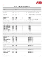
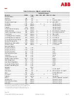
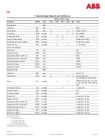
Page 137: ...used or J85702H 24V PXS with GCM Interface H285 226 G64 40 ft 108967282 Used with BJC2_MSC RIB and J85501F 1 L 33 Switchmode18 or L 35 SMR with Shunt RIM J85702B 2 L 5 48V SMR Shelf with 364A 50A SMR H285 226 G61 40 ft 108967316 J85702E 1 48V 150A SMR H285 226 G63 40 ft 108967308 Used with BJC2MSC RIC and J85501F 1 L 34 Commercial RIM Commercial Rectifier voltage regulated parallel interface See T...

Page 138: ... the rectifier if necessary to operate alarm and control relays HV TR and EQ TR G W A contact closure to HVR sent from the Galaxy SC to the rectifier which is to be turned off BOOST W BR A contact closure to HVR sent from the Galaxy SC to the rectifier which is to be placed in boost mode HV BR W A contact closure to HVR sent from the Galaxy SC to the rectifier during a high voltage condition HVR W...

Page 139: ...vidual BJC2 circuit cards must not exceed 2 5V Furthermore the common mode voltage must not exceed 160VDC RTN1 G R Return signal for ACF RFA TRH and MAN This signal is the Galaxy SC reference ground Features Reference Shunt Type Shunt type informs the controller what current the shunt connected to TB100 SH and SH measures This determines how the controller will calculate plant load and battery cur...

Page 140: ...ith CRITICAL severity level active The controller sends a signal to the rectifiers to shut down in an orderly and timely fashion This alarm prevents damaging high voltage due to rectifier failure to regulate voltage High Voltage Float When the plant voltage exceeds this threshold High Float Voltage Alarm HFV is turned ON Minor LED is Turned ON PMN relay is OPERATED assuming there is no alarm with ...

Page 141: ... 4 Settings Battery Section20 221 RPM Temperature Channels Settings Monitoring Channels or Settings Battery Management 221 Bay BIC Temperature Channels Settings Monitoring Channels or Settings Battery Management 221 Controller Temperature Channel TB2 Probe 2 3 4 Settings Monitoring Channels or Settings Battery Management 20 The presence of any Battery Section even if unconfigured establishes a Pri...

Page 142: ...ant voltage is determined by non serial rectifier voltage Controller rectifier set point is only the initial setting for serial rectifiers and does not determine plant voltage Example 2 000A aggregate rated capacity of ON serial rectifiers 4 000A aggregate rated capacity of ON non serial rectifiers 4 000A load Load 67 of ON rectifiers 1 333A aggregate load of ON serial rectifiers 67 x 2 000A capac...

Page 143: ...bles the load share between serial rectifiers attached to the system Serial rectifiers are not managed to load share Serial rectifiers are managed to regulate plant voltage to the configured plant voltage set point Configuring Load Share Mode Load share mode may be configured via EasyView Gateway web pages or on front panel at MENU CONFIG LOAD SHARE MODE Network Access LAN Gateway Local and remote...

Page 144: ...significant 24 bits of the IP address are a subnet number and the least significant 8 bits are the host identifier on the subnetwork Gateway Address The IP Address of the gateway router providing network access to a device host e g 192 168 2 1 Host Name A label assigned to a device e g plant1 Domain Name Name of the domain to which the controller is connected e g ge com Together the Host Name and ...

Page 145: ...l voltage reduction of 0 17 volts times the number of cells in the battery plant The slope thermal compensation feature uses the highest battery temperature measured See the Battery Temperature Measurement section for details STC Enables Disables the Slope Thermal Compensation feature LOW TEMP Temperature at which the plant voltage will have raised 0 1 volts x the number of cells Valid range is 23...

Page 146: ...alue Multiplier of measured voltage to displayed voltage Set as a parameter Units displayed after scaled numeric value Set as a text parameter Offset positive or negative offset to scaled numeric value Displayed Value Displayed Value Measured Voltage x Scale Factor Offset followed by Units text Measured Voltage is the value determined by the input voltage external resistors and the Range parameter...

Page 147: ...Restore Config EasyView File Backup or Restore ftp Backup Procedure from a PC requires a network card in the Galaxy SC 1 Open a Command window DOS window 2 Change Directory CD to the directory to receive the configuration file to be restored 3 Connect an ftp program to the controller e g ftp 172 16 11 5 4 Login to Galaxy SC as a super user 5 Change Directory CD to config cd config 6 GET the file c...

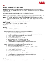
Page 148: ...ing an ASCII transfer hit any key to indicate that you are ready for the data The backup session terminates automatically with a message indicating that the backup was completed or not Restore Procedure 1 Login as a super user 2 Enter the RESTORE command 3 Select either Xmodem or ASCII transfer 4 Start your terminal upload program The restore session terminates automatically with a message indicat...

Page 149: ...Page 149 Copyright 2023 ABB All rights reserved Millennium SC_MAN Rev 2 0 This page is intentionally blank ...

Page 150: ...ibute may be modified using the CHA command its value will be reported using the CON command and it will be included in a backup Note that the value of any attribute may be acquired by using the STA commands Unless otherwise noted default values are in bold type For ranges of numeric values 1 80 8 indicates a valid range or 1 to 80 and the default 8 Values with separate ranges for 24V and 48V plan...

Page 151: ...T date X X per DTF Controller Year YRS number X 2000 2100 Controller Month MON number X 1 12 Controller Day DAY number X 1 31 Date Format DTF text X X X mm dd yy dd mm yy yy mm dd mm dd yy dd mm yy yy mm dd mm dd yyyy dd mm yyyy yyyy mm dd mm dd yyyy dd mm yyyy yyyy mm dd System Time TIM time X X hh mm Controller Hour HRS number X 0 23 Controller Minute MIN number X 0 59 Controller Second SEC numb...

Page 152: ...nable Front Panel Pin Time out FPT number X X X 1 120 minutes Front Panel PIN FPP text X X 4 digit PIN only viewable as admin Restart all RSS number X X 1 do restart rectifiers and ringers Lamp test LTT number X X 1 do lamp test System alarm state AST text NORM RO WRN MIN MAJ CRIT Port security level Access level of this session SLV text USER SUPER USER ADMINISTRATOR Daylight saving start DSS text...

Page 153: ...ription DES text X X X Local Display 1 Table 47 DC Distribution Objects and Attributes Related Commands Attribute MNEM Type CHA OPE MET CON BU Value DC Distribution Feeder FEE Identifier IDE text LDA Description DES text X X X DC Distribution Feeder Distribution Fuse DFA attrl Table 48 AC Distribution Objects and Attributes Related Commands Attribute MNEM Type CHA OPE MET CON BU Value AC Distribut...

Page 154: ...number X X X 0 no 1 yes Test Controller CTLR number X X X 0 no 1 yes Test User Relay 1 UR1 number X X X 0 no 1 yes Test User Relay 2 UR2 number X X X 0 no 1 yes Test User Relay 3 UR3 number X X X 0 no 1 yes Email Test ETS number X X 1 do test sets and clears ATA1 Email Results EMS text Individual Relay Test State IRT text X X Stop Test HVSD RFAT PCR PMJ PMN MJF MNF BD ACF RFA HV CTLR UR1 UR2 UR3 S...

Page 155: ... Transfer 1 start Manual Transfer All Rectifier On Threshold ROT number X X X 20 25 22 or 40 50 44 V Rectifier On Delay ROD number X X X 0 60 10 minutes Transfer Standby TRF number 0 inactive 1 active 0 inactive 1 active Initial Engine Transfer Delay ITD number X X X 1 600 1 seconds Transfer Sequence Interval TSI number X X X 0 1 600 1 0 seconds Universal Battery Temperature UBT text Temperature C...

Page 156: ...Phase or Low Output PHA attrl PHA1 Low Current LCA attrl LCA1 Load Share Fuse LSF attrl LSF1 Manual Off MAN attrl MAN1 External Transfer Shutdown ETS attrl ETS1 Rectifier Incomplete Config RIC attrl RIC1 Half Power HPA attrl HPA1 ID Conflict DID attrl DID1 Rectifier Current Limit CLM attrl CLM1 Very Low Voltage VLV VLA attrl VLA1 Mult Rectifier Fail MRFA MFA attrl MFA1 Limited Recharge LMR attrl L...

Page 157: ...4 bb 01 32 Description DES text X X X Voltage v Bay b Bay Voltage VAL number X number V Bay Temperature Monitor BTM Identifier IDE text BTMttbb tt 01 bb 01 32 Description DES text X X X Temperature t Bay b Bay Temperature VAL number X number C or F Is Battery Temperature IBT number X X X 0 not battery temperature 1 is battery temperature Table 52 Boost Objects and Attributes Related Commands Attri...

Page 158: ...oost Current Limit BCL number X X X 30 110 Slope Thermal Compensation STC Identifier IDE text SC1 Description DES text X X X Slope Thermal Comp Status STT number X X X 0 disable 1 enable Raise Voltage Enable RVE number X X X 0 disable 1 enable Lower Temperature Threshold LTT number X X X 5 20 C or 23 68 F Nominal Temperature Threshold NTT number X X X 15 30 C or 59 86 F Upper Temperature Threshold...

Page 159: ...er V AC Input Current AAC number X number A AC Input Current Phase 1 AAC1 number X number A AC Input Current Phase 2 AAC2 number X number A AC Input Current Phase 3 AAC3 number X number A Temperature TMP number X number F or C MAN Type MNT text X X X CC CO NONE Use In Sequence Enable SEQ number X X X 0 no 1 yes Output Breaker State OCB text CLOSED OPEN Rectifier Fail RFA number 0 inactive 1 active...

Page 160: ... X X 0 disable 1 enable Converter restart RSS number X X 1 do restart Alarm Sub Objects Converter Fail Alarm CFA attrl CFA1 Converter Fan Minor CFN attrl CFN1 Converter Fan Major CFJ attrl CFJ1 Distribution Fuse Alarm DFA attrl CDFA1 Id Conflict DID attrl CDID1 Incompatible Converter ICC attrl ICC1 Multiple Convert Fail Alarm MFA attrl CMFA1 High Voltage Alarm HVA attrl CHVA1 High Float Voltage Al...

Page 161: ...N1 Ringer ID Conflict RCDP attrl RCDP1 Ringer Chassis RCH Identifier IDE text RCn 1 8 Description DES text X X X Ringer Chassis n Status STT number X X ON STANDBY VACANT OFF MISSING with reasons FAIL TA EXT RF EXT FAN REDUN DUP Volt Amps Output VA number X number VA Primary ringer PRI number sp28 Secondary ringer SEC number sp28 Ringer Fail RF number 0 inactive 1 active Ringer Fan Fail RPFF number...

Page 162: ...State BTS text X X 0 inactive 1 active Battery Test Enable BTE number X X X 0 disable 1 enable Manual test type MTT text X X X DISABLED 20 TIMED Manual test alarm voltage TEV number X X X 21 27V or 36 48 V Manual test duration TMD time X X X 00 00 00 23 59 59 hh mm ss Battery test rectifier voltage BTV number X X X 21 26 or 42 52 V Auto test start hour ATH number X X X 0 23 Auto test interval TIN ...

Page 163: ...dentifier IDE text Bnn 01 to 70 Description DES text X X X Battery Section n Contactor CON text X X X CN1 or CN2 default Status STT text DISCON CONNECT UNKNOWN Number of Strings NST number X X X 1 70 Section Battery Type BTY text X X X From list of defined types Section Nominal Capacity CAP number number Ah Reserve Time RTM time hh mm DC Current ADC number X number A Install Date DAT date X X X da...

Page 164: ...hreshold DTH number X X X 20 25 22 or 40 50 44 V Disconnect delay DDY number X X X 0 300 minutes Disconnect automode DAM number X X X 0 NONE 1 VOLTAGE 2 VOLTAGE TIME Disconnect remaining time DTM number 0 means going to disconnect Reconnect Threshold RTH number X X X 19 5 27 24 or 39 55 48 V Reconnect delay RDY number X X X 0 300 minutes Reconnect automode RAM number X X X 0 NONE 1 VOLTAGE 2 VOLTA...

Page 165: ... AUXn Auxiliary n 1 6 EMD1 Energy Management Disabled CPA1 Circuit Pack Fail BTJ1 Battery Thermal Major EPD1 Excess Plant Drain EPR1 External Password Reset AMJ1 Auxiliary Major SNC1 Shunt Not Configured PFD1 Password At Default AMN1 Auxiliary Minor URC1 User Relay Conflict EXL1 Excessive Login Attempts FAJ1 External Fuse Major ZID1 ID Not Configured BBL1 Memory Backup Battery Low FAJ2 External Fu...

Page 166: ...ncomplete Config AAC1 ACO Active RPXN1 Ringer Minor External Fault HPA1 Half Power ATA1 Alarm Test Active RCDP1 Ringer ID Conflict DID1 ID Conflict ATF1 Alarm Test Failed CNO1 Contactor 1 Open CLM1 Rectifier Current Limit ATB1 Alarm Test Aborted CNO2 Contactor 2 Open RFN1 Rectifier Fan Fail BTA1 Battery Test Active CNO3 Contactor 3 Open CFA1 Converter Fail BFA1 Battery Test Failed CNO4 Contactor 4...

Page 167: ...ext X X X P1 P2 P3 P4 IDE Default Description Threshold THR Value Range VLA1 Very Low Voltage 20 25 5 23 or 40 51 46 V MFA1 Multiple Rectifier Fail 2 24 2 LMR1 Limited Recharge 0 5 1 0 0 8 ERD1 Excess Rectifier Drain 1 0 2 0 1 18 ETO1 Engine Transfer Timeout 0 60 30 minutes RPI1 Rectifier Plant Inconsistency 1 0 2 0 1 05 RTL1 Reserve Time Low 0 99 59 2 hours RRTL1 Real Time Reserve Low 0 99 59 2 h...

Page 168: ...ber LED LED text X X X BATT BD DIST RECT AC RM or CTLR Contact Closure ACC text X X X ACF MJF MNF RFA VLV HV BD CTLR UR1 or UR2 Notify Delay DLY number X X X 0 540 seconds Notify On Occur NOO number X X X 0 no 1 yes Notify On Retire NOR number X X X 0 no 1 yes NAG On Occur NAG number X X X 0 no 1 yes Notify Destination DST text X X X P1 P2 P3 P4 Threshold Voltage Ranges IDE Default Description Flo...

Page 169: ...nn 01 32 Description DES text X X X Timer Event n Status STT number 0 inactive 1 active Date DAT date X X X date Time TIM time X X X time default 11 59am Duration DUR number X X X 1 1440 minutes Maintenance Reminder MRM Identifier IDE text MRnn nn 1 12 Description DES text X X X Maintenance Reminder n Alarm State AST text 0 not active 1 active Severity SEV text WRN Notify On Occur NOO number X X X...

Page 170: ...g State POL text X X X CLOSED OPEN Built in Controller Plant Inputs Object Default Description In001 General Input 1 In002 LBF Input In003 RBRPO Input In004 PBT Input In005 TFLT Input In006 TBST Input In007 General Input 4 In008 LVD1 General Input 2 In009 LVD2 Input In010 LVD3 General Input 3 IN011 General Input 5 IN012 RO Input IN013 TR1 Input IN014 TR2 Input IN015 TR3 Input IN016 TR4 Input IN017...

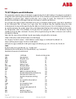
Page 171: ...eporting Enable REN number X X X 0 disable 1 enable Connect Baudrate BDR text X X X 300 1200 2400 4800 9600 19200 Data Bits DBT number X X X 7 8 Parity PRY text X X X O E N Stop Bits SBT number X X X 1 2 Handshake HSH text X X X NO SW HW Monitor DSR Signal DSR number X X X 0 no 1 yes Alarm Header Length HDR number X X X 0 100 lines Attention Prompt APR text X X X 12 char default r r Password PWD t...

Page 172: ...YPE CONFLICT Channel Type TYP text VTM Range RNG text text Value VAL number X number33 UNI Unit UNI text X X X 5 chars default V Offset OFS number X X X 99999 99999 0 Scale Factor SCF number X X X 99999 99999 1 Measurement Out Of Range MOR number 0 no 1 yes Shunt Monitor SHM Identifier IDE text Cchh c 1 6 h 0 9 A F Description DES text X X X Shunt Chan c Addr hh Status STT text ATTACHED DETACHED F...

Page 173: ...le hh Status STT text ATTACHED DETACHED FAIL TYPE CONFLICT Channel Type TYP text BIM Value VAL text X CLOSED OPEN Measurement Out Of Range MOR number 0 no 1 yes Table 65 Distribution Current Objects and Attributes Related Commands Attribute MNEM Type CHA OPE MET CON BU Value Distribution Current DCM Identifier IDE text DCMC1 is the plant shunt DCMnn 01 06 Description DES text X X X DCMC1 Plant Cur...

Page 174: ...X 99999 99999 1 Temperature Monitor Controller Temperature Channel CTC Identifier IDE text CTn 1 4 Description DES text X X X Temperature Chan n IS Battery Temperature IBT number X X X 0 not battery temperature 1 is battery temperature Value VAL number X number C or F 35 Value InputVoltage x ScaleFactor Offset 36 Value InputVoltage x ScaleFactor Offset Table 67 Other Measurement Objects and Attrib...

Page 175: ...00 1200 2400 4800 9600 19200 Data Bits DBT number X X X 7 8 Parity PRY text X X X O E N Stop Bits SBT number X X X 1 2 Pager Id Delay DLY number X X X 0 9 seconds Pager ID Pin PGR text X X X digit up to 25 characters default Pager Message MSG text X X X Email Address COE Identifier IDE text En 1 4 Description DES text X X X Email Address n Email Address ADR text X X X Type TYP text X X X NORMAL PA...

Page 176: ...m Port 1 Status STT text USER SUPER USER ADMINISTRATOR TL1 LOGOUT Data Bits DBT number X X X 7 8 Parity PRY text X X X O E N Stop Bits SBT number X X X 1 2 Time Out TMO number X X X 0 disabled 45 5 minutes Handshaking HSH text X X X NO SW Number of Rings Before Answer NRG number X X X 2 15 Write Enable WRE number X X X 0 disable 1 enable HW SW Modem Initialization String INS text X X X up to 40 ch...

Page 177: ...y Port 1 Status STT text USER SUPER USER ADMINISTRATOR TL1 LOGOUT Baudrate BDR text X X X AUTO 300 1200 2400 4800 9600 19200 Data Bits DBT number X X X 7 8 Parity PRY text X X X O E N Stop Bits SBT number X X X 1 2 Time Out TMO number X X X 0 disabled 45 minutes Handshaking HSH text X X X NO SW HW Application APP text X X X TERMINAL TL1 EVENT LOG Write Enable WRE number X X X 0 disable 1 enable HW...

Page 178: ...able 1 enable CTS Connect Detection CTS number X X X 0 disable 1 enable DSR Connect Detection DSR number X X X 0 disable 1 enable Port PRT number X X X 2020 Timeout TMO number X X X 0 60 minutes TL1 Object TL1 Identifier IDE text TLnnn 001 to 256 Description DES text X X X TL1n Condition Description CDS text X X X Condition Description Aid AID text X X X AID1 Condition Type CND text X X X Conditio...

Page 179: ...Lnn 01 15 text X X X Alarm Cut Off ACO Identifier IDE text ACO1 Description DES text X X X Alarm Cut off Status STT number X X 0 disable 1 enable Critical ACO State CST number 0 inactive 1 active Critical ACO Enable CAE number X X X 0 disable 1 enable Critical ACO Timeout CTO number X X X 1 4 hours Major ACO State JST number 0 inactive 1 active Major ACO Enable JAE number X X X 0 disable 1 enable ...

Page 180: ...Page 180 Copyright 2023 ABB All rights reserved Millennium SC_MAN Rev 2 0 This page is intentionally blank ...

Page 181: ... administrator for operation in DHCP Static mode Gateway IP Address 0 0 0 0 must be configured as instructed by the customer s network administrator for operation in DHCP Static and Client modes Subnet Mask 255 255 255 0 must be configured as instructed by the customer s network administrator for operation in DHCP Static and Client modes Host Name blank Domain Name blank DIP Switch Settings MSC ha...

Page 182: ...enhanced remote security is enabled and disabled with DIP switch SW202 6 The functions and parameters restricted with the enhanced remote security feature are listed in this table Enable or disable Rectifier Restart feature Change All Rectifier On Threshold Change Timed Manual Boost Duration Change Boost Current Threshold Change Rectifier Status to Standby Vacant status is prohibited The change to...

Page 183: ... Fail Alarm Threshold and Severity Change Battery On Discharge Alarm Threshold and Severity Voltage Threshold Ranges and Default Values Table 75 Voltage Threshold Ranges and Default Values Threshold Low High Default Very Low Voltage VLV 24V 20 00 25 50 23 00 48V 40 00 51 00 46 00 Battery on Discharge BD 24V Float 23 00 28 00 25 00 24V Boost 23 00 28 00 25 00 48V Float 46 00 55 00 51 00 48V Boost 4...

Page 184: ...BD BD BTJ Battery Thermal Major Major BAT None BTN Battery Thermal Minor Minor BAT None CCH Configuration Changed RO None None CDFA Converter Distribution Fuse Major RECT MJF CDID Converter ID Conflict Major RECT None CFA Converter Fail Minor RECT None CLC Clock Changed RO None None CMA Minor Communications Failure Minor CTLR None CMFA Multiple Converter Fail Major RECT None CNF1 Contactor 1 Faile...

Page 185: ...ct Minor BAT None LVDA Low Voltage Disconnect Fail Minor BAT None MCM Major Communication Fail Minor CTLR None MDF Module Failure Minor RM None MOR Measurement Out Of Range Minor RM None MTC Module Type Conflict Warning None None NNC Number Not Configured Warning None None OSA Open String Minor BAT None PFD Password At Default Warning None None PGI Program Line Invalid Major None None PHT Processo...

Page 186: ...Rectifier Incomplete Config Warning None None RFA Rectifier Fail Minor RECT RFA Table 78 MSC Spare and Replacement Parts Ordering code Part Description CC109130630 MCR1B MCR2B Cards May not be ordered separately CC109170123 BSL 3_MSC Alarm Card CC109170131 BSL 4_MSC Alarm Card CC109112257 BSM6 Modem Card CC109169826 MSCB_FB Fuse Board download Easy View Software Package 406530725 1 1 3 A fuse GMT ...

Page 187: ...Page 187 Copyright 2023 ABB All rights reserved Millennium SC_MAN Rev 2 0 This page is intentionally blank ...

Page 188: ...ting controller these tables assist in determining how to transfer alarm and control signal wiring from the existing controller to the MSC Table 35 Alarm and Control Signal Names and BSL Pins Table 36 Alarm Descriptions BLS Pins and Signal Names Table 37 Alarm and Control Inputs Table 38 TR Leads and Associated Rectifiers Table 79 Galaxy SC Wiring Plan Cross Reference Table 80 MCS CCS Wiring Plan ...

Page 189: ...TB2 15 RFAC BSL 44 RFAC TB2 16 VLVC BSL 59 VLVC TB2 17 PCR AR BSL 3 PCRAR TB2 18 PCR VR BSL 4 PCRVR TB2 19 PCR ER BSL 9 PCRER TB2 20 PMJ AR BSL 10 PMJAR TB2 21 PMJ VR BSL 16 PMJVR TB2 22 PMJ ER BSL 15 PMJER TB2 23 PMN AR BSL 21 PMNAR TB2 24 PMN VR BSL 22 PMNVR TB2 25 PMN ER BSL 28 PMNER TB2 26 SI R C none TB2 27 MNFR BSL 34 MNFR TB2 28 MJFR BSL 33 MJFR TB2 29 BDR BSL 39 BDR TB2 30 ACFR BSL 40 ACFR...

Page 190: ...TB3 2 CTLRC BSL 53 CTLRC TB3 3 UR1C BSL 50 UR1C TB3 4 UR2C BSL 56 UR2C TB3 5 FAJ BSL 63 FAJ TB3 6 FAN BSL 65 FAN TB3 7 OS BSL 72 OS TB3 8 TR1 BSL 73 TR1 TB3 9 TR2 BSL 79 TR2 TB3 10 TR3 BSL 85 TR3 TB3 11 TR4 BSL 80 TR4 TB3 12 ETR Not used44 Not used44 TB3 13 ETRR Not used44 Not used44 TB3 14 RO BSL 77 RO TB3 15 ROR BSL 78 ROR TB3 16 LVDF BSL 84 LVD1 TB3 17 HVR BSL 46 HVR TB3 18 CTLRR BSL 52 CTLRR T...

Page 191: ...3 32 OPT1 none TB3 33 HVO BSL 48 HVO TB3 34 CTLRO BSL 54 CTLRO TB3 35 UR1O BSL 49 UR1O TB3 36 UR2O BSL 55 UR2O TB3 37 LVD BSL 84 LVD1 TB3 38 LVDR LVDR TB3 39 TBST BSL 68 TBST TB3 40 TEQ none TB3 41 BTJ none TB3 42 BTN none TB3 43 BTP BSL 83 IN 2 BTP TB3 44 BTPFLT BSL 89 IN 3 BTPFLT TB3 45 BTPDB none TB3 46 ABS2 BSL 94 ABS TB3 47 ABS4 BSL 94 ABS TB3 48 OPT2 None BSL 95 DG BSL 96 DG P500 1 THERMA TB...

Page 192: ... SIR E BSL 33 MJFR TB1 15 SI F BSL 30 PMNEO TB1 16 SIR F BSL 28 PMNER TB1 17 SI G BSL 13 PMJEO TB1 18 SIR G BSL 15 PMJER TB1 19 FAN BSL 65 FAN TB1 20 FAJ BSL 63 FAJ TB1 21 ABS0 BSL 93 ABS TB1 22 FG Chassis Lug or FG Chassis Lug or FG TB1 23 ABS1 BSL 94 ABS TB1 24 A none none TB1 25 ABS2 BSL 93 ABS TB1 26 D none none TB1 27 ABS3 BSL 94 ABS TB1 28 BD45 BSL 38 BSL 39 BDR must be grounded BDC45 TB1 29...

Page 193: ... 37 PMJ BSL 11 PMJAC TB1 38 PMJR BSL 10 PMJAR TB1 39 PMJV BSL 17 PMJVC TB1 40 PMJVR BSL 16 PMJVR TB2 RB RB TB100 RB RB TB2 DB DB TB100 BAT BAT TB2 DG DG TB100 DG TB100 DG2 DG DG246 TB2 RG RG TB100 RG RG TB2 SH SH TB100 SH SH TB2 SH SH TB100 SH SH 46 Wire DG and DG2 discharge grounds separately to provide maximum meter accuracy If this is not possible install a jumper between DG and DG2 terminals ...

Page 194: ...6 HVEO 48 HVO TB102 7 ACFC 41 ACFC TB102 8 ACFR 40 ACFR TB102 9 ACFO 42 ACFO TB103 1 PMNAC 20 PMNAC TB103 2 PMNAR 21 PMNAR TB103 3 PMNAO 19 PMNAO TB103 4 PMNEC 29 PMNEC TB103 5 PMNER 28 PMNER TB103 6 PMNEO 30 PMNEO TB103 7 MNFEC 35 MNFC TB103 8 MNFER 34 MNFR TB103 9 MNFEO 36 MNFO TB103 10 PMNVC 23 PMNVC TB103 11 PMNVR 22 PMNVR TB103 12 PMNVO 24 PMNVO TB103 13 PMJAC 11 PMJAC TB104 1 PMJAR 10 PMJAR ...

Page 195: ...BSL 10 PMJAR BSL 11 PMJAC BSL 12 PMJAO BSL 13 PMJEO BSL 14 PMJEC BSL 15 PMJER BSL 16 PMJVR BSL 17 PMJVC BSL 18 PMJVO BSL 19 PMNAO BSL 20 PMNAC BSL 21 PMNAR BSL 22 PMNVR BSL 23 PMNVC BSL 24 PMNVO BSL 25 5V BSL 26 none BSL 27 none BSL 28 PMNER BSL 29 PMNEC BSL 30 PMNEO BSL 31 MJFO BSL 32 MJFC BSL 33 MJFR BSL 34 MNFR BSL 35 MNFC BSL 36 MNFO BSL 37 BDO BSL 38 BDC BSL 39 BDR BSL 40 ACFR BSL 41 ACFC BSL...

Page 196: ...SL 49 UR1O BSL 50 UR1C BSL 51 UR1R BSL 52 CTLRR BSL 53 CTLRC BSL 54 CTLRO BSL 55 UR2O BSL 56 UR2C BSL 57 UR2R BSL 58 VLVR UR3R BSL 59 VLVC UR3O BSL 60 VLVO UR3O BSL 61 LVD2 BSL 62 LVD2R BSL 63 FAJ BSL 64 AMJ BSL 65 FAN BSL 66 AMN BSL 67 TFLT BSL 68 TBST BSL 69 TRTN BSL 70 PBTR BSL 71 PBT BSL 72 OS BSL 73 TR1 BSL 74 TEQ BSL 75 IN 5 BSL 76 IN 5R BSL 77 RO BSL 78 ROR BSL 79 TR2 BSL 80 TR4 BSL 81 RBRP...

Page 197: ...nal Name BSL 88 4 20mA R BSL 89 IN 3 BTPFLT BSL 90 USE3DETECT BTMJ BSL 91 EXT V BSL 92 EXT VR BSL 93 ABS BSL 94 ABS BSL 95 DG BSL 96 DG RB TB100 RB RB DB TB100 BAT BAT DG TB100 DG TB100 DG2 DG DG249 RG TB100 RG RG SH TB100 SH SH SH TB100 SH SH 49 Wire DG and DG2 discharge grounds separately to provide maximum meter accuracy If this is not possible install a jumper between DG and DG2 terminals ...

Page 198: ...Page 198 Copyright 2023 ABB All rights reserved Millennium SC_MAN Rev 2 0 This page is intentionally blank ...

Page 199: ... in the product documentation DC output cables must be dressed to avoid damage to the conductors caused by routing around sharp edges or routing in areas where wires could get pinched and undue stress on the connectors External protectors fuses or circuit breakers must be sized as required by the National Electric Code NEC and or local codes Refer to the equipment ratings to assure current does no...

Page 200: ...c mains voltage This symbol is used to identify the presence of hazardous ac or dc voltages It may also be used to warn of hazardous energy levels One of these two symbols or equivalent may be used to identify the presence of rectifier and battery voltages The symbol may sometimes be accompanied by some type of statement for example Battery voltage present Risk of injury due to high current Avoid ...

Page 201: ...afety warnings and practices when servicing this equipment When equipped with ringer modules hazardous voltages will be present on the ringer output connectors In addition to proper job training and safety procedures the following are some basic precautions that must always be used Use only properly insulated tools Remove all metallic objects key chains glasses rings watches or other jewelry Wear ...

Page 202: ...Page 202 Copyright 2023 ABB All rights reserved Millennium SC_MAN Rev 2 0 This page is intentionally blank ...

Page 203: ...the right to sell transfer and assign such Products and the title conveyed by Seller shall be good 2 During the warranty period stated in Sub Article B below Seller s Manufactured Products products manufactured by Seller which have been paid for by Customer will conform to industry standards and Seller s specifications and shall be free from material defects 3 With respect to Vendor items items no...

Page 204: ... Customer E Except for batteries the defective or nonconforming Products or parts which are replaced shall become Seller s property Customer shall be solely responsible for the disposition of any batteries F If Seller determines that a Product for which warranty service is claimed is not defective or nonconforming Customer shall pay Seller all costs of handling inspecting testing and transportatio...

Page 205: ...Page 205 Copyright 2023 ABB All rights reserved Millennium SC_MAN Rev 2 0 Revision Doc Rev Description Date Dept Init 1 0 Initial release April 2012 2 0 Updated as per ABB template 05 25 2023 ...

Page 206: ...oes not accept any responsibility whatsoever for potential errors or possible lack of information in this docu ment We reserve all rights in this document and in the subject matter and illustrations contained therein Any reproduction disclosure to third parties or utilization of its contents in whole or in parts is forbid den without prior written consent of ABB Copyright 2023 ABB All rights reser...

Reviews: