Page 63
© Copyright 2023 ABB. All rights reserved.
Millennium SC_MAN
Rev 2.0
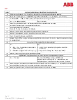
Step
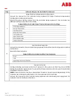
Action to Disconnect Other MCS Connections
1
Is more than 1 wire connected to TB2 pin 1 or pin 2?
Yes –
Proceed
No –
Proceed to Step 3.
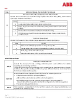
NOTE
Systems equipped with ED83018
-
31 group 17 low
-
voltage disconnect panels can operate
and disconnect an office load.
WARNING
Additional wires on these terminals could be sense leads for ED83018
-
31 group 17 low
voltage disconnect panels. If the sense leads are removed from these panels, the
contactor can operate and disconnect critical office loads. Therefore, it is necessary to
determine what they feed and their function.
2
Are wires connected to TB2 pin 1 or Pin 2 used as sense leads for ED83018
-
31 group 17 low
voltage disconnect panels?
Yes –
1.
Place jumpers on the wires before
disconnecting them from TB2.
2.
Proceed
No –
Proceed.
3
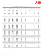
Record wire colors of all wires to be removed in Table 80 MCS/CCS Wiring Plan & Cross
Reference.
4
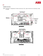
Twist together the normally closed alarm leads after disconnecting the existing alarm leads
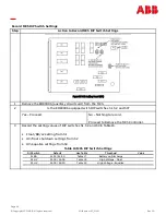
from the MCS terminal block TB1. See Figure 34 MCS TB1 Alarm Connections.
Disconnecting will prevent continuous office alarms during controller transition. For example,
twist together wires from positions 39 and 40 (PMJV and PMJVR).
5
Remove, Mark And Insulate all external wires (office alarms) terminated on TB1.
6
Cut the existing MCS alarm connections at TB1 on the MCS controller.
Leave adequate length for reconnection to MSC.
Alarm connections on MSC do not require crimped connections.
7
Remove fuses F17 to F22 from the controller.
8
Disconnect from the energy source, insulate, and label these leads:
•
Regulation battery (RB)
•
Discharge battery (DB)
•
SH+
•
SH –
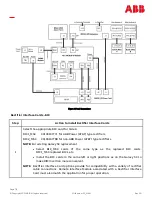
9
Disconnect from MCS TB2, insulate, and label these leads:
•
Regulation battery (RB)
•
Discharge battery (DB)
•
Discharge ground (DG)
•
Regulation ground (RG)
•
SH+
•
SH –
Is the controller equipped with a shunt isolator circuit card?
10
Yes –
Isolate or Disconnect the shunt isolator
circuit card. This is located behind the blank
panel below the controller.
No –
Continue.
11
Verify that no voltage exists on MCS TB2. Disconnect and label all remaining wires terminated
on TB2.
12
Remove, Mark and Insulate any external wires terminated on the optional side of the
backplane. Examples follow:
•
Telephone lines
•
Remote interface cables
Make sure that office records are present. Refer to Table 80 MCS/CCS Wiring Plan & Cross
Reference.


