background image


Page 18


© Copyright 2021 ABB. All rights reserved. 


Français 

-

 French


Instructions d'installation


(Installation Instructions)


· 

Tension d'entrée (Input Voltage):


        200 

-

 277/200 

-

 277, 3W + PE/380 

-

 480, 3W + N + PE (H569 

-

 4827)


       200 

-

 240/200 

-

 240, 3W + PE/380 

-

 480, 3W + N + PE (H569 

-

 434)


       380 

-

 480, 3W + PE (H569 

-

 4830) 


· 

Courant d'entrée (Input Current):


       22A/rectifier/104Amax/88Amax (H569 

-

 4827)


       22A/rectifier/120Amax/75Amax. (H569 

-

 434)


· 

32Amax (H569 

-

 4830)Fréquence (Frequency): 50/60Hz 


· 

Les dimensions sont pour référence seulement:


       (Dimensions are for reference only:) 


       600mm x 600mm


· 

Max. température de fonctionnement:


      (Max. operation temperature:)


       40°C (104°F) for H569 

-

 434 and H569 

-

 4827


      35°C (95°F) for H569 

-

 4830 Types GZ1, GZ8 

-

 GZ10, GZ20, and GZ21


      45°C (113°C) for H569 

-

 4830 Types GZ2 

-

 GZ7, GZ17 

-

 GZ19


· 

ATTENTION:  Pour  ne  pas  compromettre  la  protection contre  les risques  d’incendie,  remplacer  par 

un fusible de même type et de mêmes caractéristiques nominales.


· 

Alimentation est un équipement de classe I


(Power Supply is a Class I Equipment)


Special Installation Notes 

(continued)


Summary of Contents for Galaxy Power System

Page 1: ... Guide for Galaxy Power Systems Note Instructions in this manual reference installation and setup of GPS 4848 100 GPS 4827 and GPS 4830 power systems using the Millennium II Controller For installation and setup with other controllers and rectifiers refer to their product manuals ...

Page 2: ...ish 16 Français French 18 3 Getting Started 20 Tools and 20 Torque Settings for Hardware 21 Table 3 A Torque Settings for Hardware 21 Unpacking Location 21 4 System Electrical Architecture Overview 22 Introduction 22 Bonding Network 22 Facility 22 Single Cabinet Distributed System 22 Distributed Architecture 23 Centralized Architecture 25 5 Cabinet Floor Mounting and Grounding 27 Cabinet Installat...

Page 3: ...ennium II Controller 47 BLJ2 3 to BIC10 or BIC10 to BIC10 Millennium II Controller 48 BLJ2 3 to BIC11 or BIC11 to BIC11 Millennium II Controller 49 Bay ID and Shunt Size Configuration 50 BLJ2 3 Millennium II Controller 50 BIC10 Millennium II Controller 51 BIC11 Millennium II Controller 52 Millennium II Controller Configuration of BIC Shunt Channels 53 Software Configured Bay Current Shunt Channel ...

Page 4: ... Phase Neutral Input Cir cuits ED83142 30 G7 or G28 80 Wiring charts for GPS 4827 81 Wiring charts for GPS 434 82 Wiring charts for GPS 4830 84 Bottom CableFeed Options for GPS 4848 100 Systems 86 Completing the AC Connection 87 Notes 87 8 DC Distribution Assembly and Connections 88 Overview 88 DC Distribution Panels Cross Reference 89 Table 8 A DC Distribution Panels Cross Reference 89 Connecting...

Page 5: ...ce Alarms 130 Introduction 130 Connecting Controller Alarms 130 13 Power Up and Installation Completion 132 Initial System Checkout and Preparation for Power Up 132 Before Installing Rectifiers 132 Safety Reminder 132 Controller Front Panels 132 Illustrations 132 Initial Power Up of the System 133 Rectifier Installation Notes 133 Installing the First Rectifier 134 Verify Controller 134 Set Rectifi...

Page 6: ... This Installation Guide This Installation Guide provides instructions for installing GPS 4848 100 GPS 4827 and GPS 4830 Power Systems Ordering Guide H569 4827_4830_434 Manufacturing Drawings ED83142 30 AC ED83143 31 DC J85582C 1 System Wiring Diagram T83314 30 Manufacturing Drawing J85501P 1 Product Manual 108994645 Manufacturing Drawing J85501G 1 Wiring Diagram T83275 30 Schematic Drawing SD 832...

Page 7: ... include initiating the spare parts procurement process ordering documents product warranty administration and providing other product and service information For other customers worldwide contact your local field support center or your sales representative to discuss your specific needs Customer Training ABB offers customer training on many Power Systems products For information call 1 972 244 92...

Page 8: ...4 Rectifiers are also approved to IEC60950 1 EN60950 1 2006 A11 A1 A12 A2 by an EC Notified Body and have outputs classified as SELV Install only in restricted access areas dedicated equipment rooms equipment closets or the like in accordance with articles 110 16 110 17 and 110 18 of the U S National Electric Code NEC ANSI NFPA No 70 and pursuant to applicable local codes Rules and Regulations Fol...

Page 9: ...ded obtain appropriate connectors and follow manufacturer s and all local requirements for proper connections Battery input cables must be dressed to avoid damage to the conductors caused by routing around sharp edges or routing in areas where wires could get pinched and undue stress on the connectors Field wired Conductors Follow all National Electric Code NEC and local rules and regulations Sele...

Page 10: ... symbol is used to identify the presence of hazardous ac or dc voltages It may also be used to warn of hazardous energy levels One of these two symbols or equivalent may be used to identify the presence of rectifier and battery voltages The symbol may sometimes be accompanied by some type of statement for example Battery voltage present Risk of injury due to high current Avoid contacting conductor...

Page 11: ...ectifiers Turning off the rectifiers will not necessarily remove power from the bus High leakage currents may be possible on this type of equipment Make sure the equipment is properly safety earth grounded before connecting power Exercise care and follow all safety warnings and practices when servicing this equipment Hazardous energy and voltages are present in the unit and on the interface cables...

Page 12: ...3 feet 12 feet 30 feet 1 0 GA 50 mm2 5 feet 19 feet 2 0 GA 70 mm2 6 feet 24 feet 4 0 GA 120 mm2 10 feet 38 feet 2 4 0 GA 2 120 mm2 19 feet 76 feet 3 4 0 GA 3 120 mm2 29 feet 113 feet 350 MCM 17 feet 63 feet 2 350 MCM 32 feet 125 feet 3 350 MCM 47 feet 188 feet Precautions continued Table 2 B Interrupt Current Ratings for Fuses and Circuit Breakers Description ED83143 31 Groups Interrupt Current Ra...

Page 13: ...ety procedures the following are some basic precautions that should always be used Use only properly insulated tools Remove all metallic objects key chains glasses rings watches or any other jewelry Follow Lock Out Tag Out LOTO procedures customer specified site specific or general as appropriate Disconnect all power input before servicing the equipment Check for multiple power inputs Wear safety ...

Page 14: ...4Amax 88Amax H569 4827 22A rectifier 120Amax 75Amax H569 434 32Amax H569 4830 Nennfrequenz Frequency 50 60Hz Abmessungen sind nur zur referenz Dimensions are for reference only 600mm x 600mm Max Umgebungstemperatur Max operation temperature 40 C 104 F for H569 434 and H569 4827 35 C 95 F for H569 4830 Types GZ1 GZ8 GZ10 GZ20 and GZ21 45 C 113 C for H569 4830 Types GZ2 GZ7 GZ17 GZ19 Achtung Für kon...

Page 15: ...or 5 conductor systems Das Gerät hat keinen eigenen Ausschalter es muß daher mit einem Ein und Ausschalter im Versorgungskreis versehen sein Mains disconnect switch required in the installation Das Gerät hat kein Brandschutzgehäuse es darf daher nur auf nicht brennbaren Untergrund aufgestellt werden Beton Metall usw No fire enclosure must be mounted on non combustible surface Das Gerät wird fest a...

Page 16: ...A rectifier 120Amax 75Amax H569 434 32Amax H569 4830 Frecuencia Frequency 50 60Hz Las dimensiones son únicamente para referencia Dimensions are for reference only 600mm x 600mm Temperatura máxima de operación Max operation temperature 40 C 104 F for H569 434 and H569 4827 35 C 95 F for H569 4830 Types GZ1 GZ8 GZ10 GZ20 and GZ21 45 C 113 C for H569 4830 Types GZ2 GZ7 GZ17 GZ19 Advertencia Para una ...

Page 17: ...or systems Se requiere un interruptor de desconexión de la línea principal en la instalación Mains disconnect switch required in the installation Sin cabina contra incendios suelo no combustible No fire enclosure must be mounted on non combustible surface Debe estar anclado al piso Must be bolted to the floor Voltaje Corriente H569 434 48 VDC 14 080 A H569 4830 48 VDC 6400 A H569 4827 48 VDC 9600 ...

Page 18: ...réquence Frequency 50 60Hz Les dimensions sont pour référence seulement Dimensions are for reference only 600mm x 600mm Max température de fonctionnement Max operation temperature 40 C 104 F for H569 434 and H569 4827 35 C 95 F for H569 4830 Types GZ1 GZ8 GZ10 GZ20 and GZ21 45 C 113 C for H569 4830 Types GZ2 GZ7 GZ17 GZ19 ATTENTION Pour ne pas compromettre la protection contre les risques d incend...

Page 19: ...veloppe électrique interrupteur de sectionneur requis dans l installation Mains disconnect switch required in the installation Aucune enceinte d incendie doit être monté sur une surface non combustible No fire enclosure must be mounted on non combustible surface Doit être boulonné au sol Must be bolted to the floor Voltaje Corriente H569 434 48 VDC 14 080 A H569 4830 48 VDC 6400 A H569 4827 48 VDC...

Page 20: ... wrench provided Insulated hand tools Screw drivers flat blade and Phillips Wire cutters and stripper Torque wrenches see Table 3 A 35 513 in lbs 4 58 N m Sockets Metric English Equivalent Hardware 8mm 5 16 M5 10mm M6 13mm 1 2 M8 17mm 11 16 M10 19mm 3 4 M12 3 8 1 4 9 16 3 8 Crimp tools 22 16 gauge 10 500 MCM 5 120mm2 Jeweler s screwdriver Digital multimeter DMM with 0 05 accuracy on dc scale Load ...

Page 21: ...s and associated stands are in place Cable rack not supported by cabinets is in place Job Site Documentation is available that details cabinet locations dc distribution assignments and Remote Peripheral Monitoring System module location and assignment Metric Screw Size Torque N m Torque in lbs M2 0 24 2 M2 5 0 48 4 M3 0 9 8 M3 5 1 4 12 M4 2 18 M5 4 35 M6 7 62 M8 18 145 M10 34 300 M12 58 513 Englis...

Page 22: ...ork CBN or an Isolated Bonding Network IBN In this manual Battery Return grounds labeled System CO ground are Isolated DC return DC I Installation as part of a Common Bonding Network CBN or an Isolated Bonding Network IBN is determined by the point external to the GPS system connected to GPS System CO ground Facility GPS systems are suitable for installation in Network Telecommunication Facilities...

Page 23: ...imbalances between the individual cabinet loads due to improper sizing or to rectifier or battery module failure Distributed architecture is summarized as follows Each cabinet generates and distributes all the dc power it requires as a stand alone system but also has additional capacity to share power feeding or receiving with other cabinets within the plant Growth of the system is accomplished by...

Page 24: ...Page 24 Copyright 2021 ABB All rights reserved Distributed Architecture continued Figure 4 3 Three Cabinet or more Configuration Distributed Architecture ...

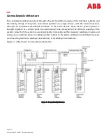
Page 25: ...ugh the centralized distribution modules to the same dc bus Since all the system power is brought together at a central point the central point must be sized for the ultimate capacity of the system Growth of the system is accomplished by increasing rectifier capacity adding ac inputs and shelves to an existing cabinet or adding another cabinet to the plant adding more distribution panels to an exi...

Page 26: ...itored by BIC or PIC shunt channels must include CLRs in the monitoring path Refer to Section 6 for details Note The batteries and rectifiers are all connected to a common bus in this power system configuration The plant s total load is determined by the system controller from the readings taken from the single system current shunt located in the common bus Some of the common Centralized Architect...

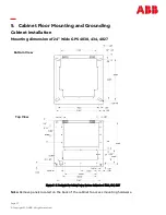
Page 27: ...on of 24 Wide GPS 4830 434 4827 Figure 5 1 Footprint for Galaxy Power System Cabinets of 4830 434 4827 5 Cabinet Floor Mounting and Grounding Cabinet Installation Note Remove panels located on the back of the cabinet to access mounting hardware Top View Bottom View ...

Page 28: ...ll rights reserved Mounting dimension of 36 wide GPS 4830 434 Figure 5 2 Footprint for Galaxy Power System Cabinets of 4830 434 Note Remove panels located on the back of the cabinet to access mounting hardware Bottom View Top View ...

Page 29: ...BB All rights reserved Mounting dimension of 30 Wide GPS 4827 Figure 5 3 Footprint for Galaxy Power System Cabinets of 4827 Note Remove panels located on the back of the cabinet to access mounting hardware Bottom View Top View ...

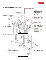
Page 30: ...19mm 720 in lbs 60 ft lbs 81 6 N m 0 1 2 3 4 847135688 4 12mm cap bolts 18mm 100mm deep 19mm 720 in lbs 60 ft lbs 81 6 N m Cabinet Installation continued Procedure Refer to Figure 5 4 5 for this procedure Cabinet Installation Step Action Position the appropriate drill template where the cabinet is to be located Comcode of Template 847891280 Using a drill bit drill anchor holes to the depths specif...

Page 31: ...d 4 Two opposite corners for zones 0 1 and 2 Threaded Rod 5 8 847837879 Fascia cover or 84285854 RPM Fascia cover 901015461 4 Nuts 8 32 Left End of line up only optional Single cabinet or cabinet at Left End of line up only Fascia cover 847837879 GPS4848 100 848513594 GPS2424 30 GPS4812 24 901015461 4 Nuts 8 32 Right End of line up only optional 847891264 adapter to 5 8 threaded rod to be used if ...

Page 32: ...nd for Distributed Architecture Step Action Run and connect the system ground lead to the initial cabinet return bus This connection will connect the re turn side of the dc system to earth ground Torque connections as specified in Figure 5 6 Cabinet Ground Procedure The next step is to ground the cabinet framework Local grounding practices will determine the grounding method and the size of cable ...

Page 33: ...Page 33 Copyright 2021 ABB All rights reserved Figure 5 6 Full Height Cabinet and System Central Office Ground Cabinet Ground and Central Office Ground Continued ...

Page 34: ...Page 34 Copyright 2021 ABB All rights reserved Recommended Cable Rack Layout Figure 5 7 Various Cable Rack Arrangements ...

Page 35: ...Page 35 Copyright 2021 ABB All rights reserved Notes ...

Page 36: ... alarm and serial bus connections Centralized Architecture Introduction This section covers the field assembly for Centralized Architecture DC power connections to central bus bar Refer to Figure 6 1 for this procedure DC power connections to central bus bar Step Action 1 Install optional plates if more than 8 connections are needed See Figure 6 1 2 Run and connect new wires from positive and nega...

Page 37: ...Page 37 Copyright 2021 ABB All rights reserved To Centralized Charge Ground Bus Bar Figure 6 1 DC Power Connections to Centralized Bus Bars Centralized Architecture continued ...

Page 38: ...nts M1 SH violet wire and M2 SH white wire on the BLJ termination board Limit the resistance of this wiring to 1 ohm maximum Typically this may be accomplished with 22 AWG conductors 25 ft long 1 way or 20 AWG conductors 45 ft long 1 way If the cabling distance to the shunt exceeds these lengths then 12 AWG conductors may be used and spliced down to 22 AWG within the wiring gutter above the BLJ ca...

Page 39: ...ew wires from the central bus bars Connect to the BIC 10 TB1 1 RB and TB1 2 RG Move the VSns Jumpers at J20 Bat Sns J21 DG Sns from LCL to RMT System Shunt for Millennium II with BIC10 Bay Board Step Action Run new wires installer provided from the system shunt to the BIC 10 TB1 3 SH and TB1 4 SH Limit the resistance of this wiring to 1 ohm maximum Typically this may be accomplished with 22 AWG co...

Page 40: ...Page 40 Copyright 2021 ABB All rights reserved Centralized Architecture Continued Figure 6 3 System Shunt and Remote Voltage Sense for Millennium II Controller in Cabinet with BIC10 Bay Board ...

Page 41: ... the BIC11 TB2 10T RB and TB2 9T RG Note If central bus bars have LVBD sense leads must be on the rectifier side of the contactor Move the VSns Jumpers at J20 Bat Sns J21 DG Sns from LCL to RMT System Shunt for Millennium II with BIC11 Bay Board Step Action Run new wires installer provided from the system shunt to the BIC11 TB2 8T SH and TB2 3B SH Limit the resistance of this wiring to 1 ohm maxim...

Page 42: ...ht 2021 ABB All rights reserved Centralized Architecture Continued Table 6 BIC 11 Terminal block positions Figure 6 4 System Shunt and Remote Voltage Sense for Millennium II Controller in Cabinet with BIC11 Bay Board ...

Page 43: ...rd and controller mounted on the cabinet door are wired to a ground terminal strip 848474185 mounted off a standoff on either the rear wall standard width J85582C1 L3 or the left side of the top front panel wide width J85582C1 L103 as indicated below In order for the BIC or M2 to be powered in these cabinets a 12 ga return lead must be extended from the external plant return bus to this ground ter...

Page 44: ... the battery strings cable back to this bus run at the rectifier cabinets and the distribution circuit returns use the bus run over the distribution cabinets keeping all circuits closely coupled in a compact growable system Each distribution cabinet in these arrangements is fed through a 6000A load shunt which is then monitored by its BIC Bay Interface Card shunt circuit utilizing the optional All...

Page 45: ...C Power Bus Connections Step Action Install the intercabinet bus bars as shown Install the bus bar shield as shown Torque connections as specified in Figure 6 5 Distributed Architecture Intercabinet DC Power Bus Connections Refer to Figure 6 5 for this procedure ...

Page 46: ... that 434 Supplemental Bays come standard with 1800A bay to bay kit All other bays require interconnect kits see ordering guide 847760204 Short T Bus Bar Negative for 48V systems 847760196 Long T Bus Bar Positive for 48V systems 848414611 Bus Bar Shield 1 per Supplemental Cabinet 847720802 Bus Bars Hardware provided 901249839 Nut M8 901249821 Lock Washer M8 901249813 Flat Washer M8 8 places each b...

Page 47: ...procedure BLJ2 3 to BLJ2 3 Millennium II Controller Step Action Connect the Rectifier Interface Cable Assembly from J5 of one BLJ2 3 board to J6 of the BLJ2 3 board in the next cabinet Note Remove and discard any resistors that are blocking access to J6 or J5 connection points except for those in J5 of the last cabinet Figure 6 6 BLJ2 or BLJ3 Board Connections Millennium Controller Intercabinet Al...

Page 48: ...tifier Interface Cable Assembly from J5 of one BLJ2 3 board to any J1 J4 of the BIC10 board in the nextcabinet or from any of J1 to J4 of one BIC 10 to any of J1 to J4 of the next BIC10 J1 to J4 are all common on the BIC10 Note Remove and discard any resistors that are blocking access to J5 connection point on BLJ2 3 board Set the J11 RS485 termination jumper to the 2 3 position in the BIC 10 of t...

Page 49: ...ctifier Interface Cable Assembly from J5 of one BLJ2 3 board to any J1 J4 of the BIC11 board in the nextcabinet or from any of J1 to J4 of one BIC11 to any of J1 to J4 of the next BIC11 J1 to J4 are all common on the BIC11 Note Remove and discard any resistors that are blocking access to J5 connection point on BLJ2 3 board Set the J13 RS485 termination jumper to the 2 3 position in the BIC11 of th...

Page 50: ...ial and must have 100K ohm CLRs Current Limiting Resistors installed at the shunt end of the circuit If the shunts to be monitored are at return bus potential instead of hot bus potential then jumper J12 immediately above S1 must be moved to the 2 3 position If the Software Configured Shunt Size is selected proceed to the next section on configuration of it using the Millennium II controller web p...

Page 51: ...tored is at return bus potential instead of hot bus potential then jumper J14 immediately below the local shunt connection must be moved to the 1 2 position Note Any shunt circuit wired to this BIC 10 local shunt circuit must have 100K ohm CLRs Current Limiting Resistors installed at the shunt end of the circuit These CLRs are provided already by the shop when the shunt circuit is pre wired If the...

Page 52: ... hot bus potential then jumper J15 for Shunt 1 or J16 for Shunt 2 must be moved to the 1 2 position Note Any shunt circuit wired to this BIC11 local shunt circuit must have 100K ohm CLRs Current Limiting Resistors installed at the shunt end of the circuit These CLRs are provided already by the shop when the shunt circuit is pre wired If the Software Configured Shunt Size is selected proceed to the...

Page 53: ... desired configuration for the shunt size and type within the Millennium II controller itself by logging in over the web pages 1 Go to the Settings Programming Monitor Channels screen Click on Monitor Channels 2 Choose the Bay Current Monitor item from the pull down menu 3 All BIC Current inputs should be listed Those with current values including zero are installed and active The BIC current moni...

Page 54: ...assigned shunt is measuring Battery string charge or discharge current in a distributed architecture plant Shunt Type will be set to Load shown above only when using the ED83311 30 overhead bus arrangements with Distribution only cabinets each fed by their own shunt When this is the case Shunt Type for Plant Current Plant Shunt 2 Current on the Settings Shunts web page below must both be set to No...

Page 55: ...eries rectifier input and output voltages are as shown below Input Rectifier Output 380 480Vac 3 phase 50 60 Hz 595A and 595LTA series 48Vdc 220A 200 240Vac 3 phase 50 60 Hz 595B and 595LTB series The GPS 4848 100 system supports three AC schemes Single bulk 3 wire 3 phase The panel is factory equipped to distribute the appropriate connections to the rectifiers through circuit breakers Multiple bu...

Page 56: ...fiers One feed for two rectifiers A suffix one feed for four rectifiers B suffix of one feed per rectifier C suffix External circuit overload protection must be provided by customer Note All wire sizes are based on the US National Electric Code GPS 4827 NE050AC48TEZ Rectifiers 48V 50A and NE075AC48TEZ Rectifier 48V 75A Infinity NE series rectifier input and output voltages are as shown below Input...

Page 57: ...n AC circuit breaker panel stating that installers are working in the AC cabling 2 Check that all AC circuit breakers are turned OFF 3 Route the AC cables to the cabinet as required by local building codes 4 At the cabinet route the AC cables through the access holes in the top of the cabinet 5 Install terminal lugs if applicable to cables Connecting AC Conduit Figure 7 1 Attaching AC Conduit Qty ...

Page 58: ...Page 58 Copyright 2021 ABB All rights reserved Rectifier Positions Figure 7 2 GPS 4848 100 Dual Shelf Rectifier Positions ...

Page 59: ...ts at bottom shelf and shelf number increases from bottom to top for cabi nets with Top AC in and Top DC out A Suffix Left most breaker feeds bottom shelf B Suffix Left most breaker feeds bottom two shelves Shelf numbering starts at bottom shelf and shelf number increases from bottom to top for cabinets with Top AC in and Top DC out A Suffix One feed for two rectifiers B Suffix One feed for four r...

Page 60: ...elf number increases from bottom to top Breakers are Numbered from left to right Left most breaker starts with bottom shelf Shelf numbering starts at bottom shelf Shelf 1 and shelf number increases from bottom to top Terminal Strips are Numbered from left to right Left most Terminal Strip starts with bottom shelf GPS 4827 With Bulk Feed AC Circuit Breaker GPS 4827 With AC Terminal Strip Feed ...

Page 61: ...0 2 6 G4A G323 22KAIC 480 4 12 G24 G334 65KAIC 480 2 4 G10 G370 65KAIC 480 2 6 G11 G371 AC Terminal Strip Panels 595LT Rectifiers 208 240 4 4 G18 G324 208 240 6 6 G18 G325 325C 208 240 8 8 G18 G331 331C 208 240 12 12 G26 G329 208 240 14 14 G26 G333 G433 480 4 4 G18 G326 480 6 6 G18 G327 327C 480 8 8 G18 G330 330C 480 12 12 G26 G328 480 14 14 G26 G332 G432 Distribution Only Panels no AC 1200A None ...

Page 62: ...p Panels GP100 Series Rectifiers 4 8 G518 G304A 2 G304B 8 G520 G304C 6 12 G518 G306A 3 G306B 12 G520 G306C 8 16 G518 G308A 4 G308B 16 G520 G308C 10 20 G518 G310A 5 G310B 20 G520 G310C 12 24 G518 G312A 6 G312B 24 G520 G312C 480 AC Circuit Breaker Panels GP100 Series Rectifiers 208 1 8 G2 4 J G384A 2 12 G3 6 J G386A AC Terminal Strip Panels GP100 Series Rectifiers 208 4 8 G521 G364A 8 G364C 6 12 G36...

Page 63: ...8ATEZ Rectifiers 208 240 1 12 G7 G031 480 N G7 N kit G031 N kit 208 240 2 24 G28 G032 W 480 N G28 N kit G032 N kit AC Terminal Strip Panels NE050AC48ATEZ Rectifiers 208 240 12 20A 12 G20 G026 6 40A 24 20A 24 G27 G027 12 40A 8 60A 36 20A 36 G028 18 40A AC Terminal Strip Panels NE075AC48ATEZ Rectifiers 208 240 G27 G036 6 60A 277 N 12 25 30A 6 50A 208 240 12 60A 24 G27 G037 W 277 N 24 25 30A 12 50A 2...

Page 64: ...ved AC Input Panels Wiring Options for ED8314230 Group 2 Figure 7 5 ED83142 30 Group 2 H569 434 G322 AC Input Panel for 595A or LTA Series Rectifiers or H569 4830 G334A or G334B AC Input Panel for GP100 Series Rectifiers Torque to 62 in lbs 7 Nm ...

Page 65: ...C Input Panels continued Wiring Options for ED8314230 Group 3 Figure 7 6 ED83142 30 Group 3 H569 434 G320 AC Input Panel for 595B or LTB Series Rectifiers or H569 4830 G346A or G346B AC Input Panel for GP100 Series Rectifiers Torque to 62 in lbs 7 Nm ...

Page 66: ...21 ABB All rights reserved AC Input Panels continued Wiring Options for ED8314230 Group 4A Figure 7 7 ED83142 30 Group 4A H569 434 G321 or G323 AC Input Panel for 595A B LTA or LTBSeries Rectifiers Torque to 62 in lbs 7 Nm ...

Page 67: ...All rights reserved Figure 7 8 ED83142 30 Group 7 H569 4827 G021 or G031 AC Input Panel for NE050AC48ATEZ or NE075AC48ATEZ Series Rectifiers AC Input Panels continued Wiring Options for ED8314230 Group 7 Torque to 62 in lbs 7 Nm ...

Page 68: ...ght 2021 ABB All rights reserved AC Input Panels continued Wiring Options for ED8314230 Group 10 Figure 7 9 ED83142 30 Group 10 H569 434 G370 AC Input Panel for 595A or LTA Series Rectifiers Torque to 62 in lbs 7 Nm ...

Page 69: ...ght 2021 ABB All rights reserved AC Input Panels continued Figure 7 10 ED83142 30 Group 11 H569 434 G371 AC Input Panel for 595A or LTA Series Rectifiers Wiring Options for ED8314230 Group 11 Torque to 62 in lbs 7 Nm ...

Page 70: ...ued Wiring Options for ED8314230 Group 18 Figure 7 11 ED83142 30 Group 18 H569 434 G324 G325 G326 or G327 AC Input Panel for 595A B LTA or LTB Series Rectifiers ISO View AC GRD connections Torque to 62 in lbs 7 Nm Terminal block connections Max Torque 19 5 in lbs 2 2 Nm ...

Page 71: ... or NE075AC48ATEZ Series Rectifiers Wiring Options for ED8314230 Group 20 Note To minimize phase imbalance voltage potentials between each 3W PE and 3W N PE field wiring terminal block group use feeds from the same transformer source AC GRD connections Torque to 62 in lbs 7 Nm L1 L2 N L2 L3 N L3 L1 N L1 L2 N L2 L3 N L3 L1 N L1 L2 N L2 L3 N L3 L1 N L1 L2 N L2 L3 N L3 L1 N L1 L2 N L2 L3 N L3 L1 N L1...

Page 72: ...put Panels continued Wiring Options for ED8314230 Groups 24 or 25 Figure 7 13 ED83142 30 Groups 24 or 25 H569 434 G334 or G335 AC Input Panel for 595LTA or LTB Series Rectifiers Recommended M6 STUD Spacing between the studs 0 75 Torque to 62 in lbs 7 Nm ...

Page 73: ... 2021 ABB All rights reserved Figure 7 14 ED83142 30 Group 26 H569 434 G328 G329 G332 G333 G432 or G433 AC Input Panel for 595LTA or LTB Series Rectifiers AC Input Panels continued Wiring Options for ED8314230 Group 26 ...

Page 74: ...Figure 7 15 ED83142 30 Groups 27 H569 4827 G026 G027 G028 G036 G037 G037W G038 G038W G308 or G308W AC Input Panel for NE050AC48ATEZ or NE075AC48ATEZ Series Rectifiers AC GRD 36 Positions AC GRD M6 STUD 0 75 Spacing AC GRD connections Torque to 62 in lbs 7 Nm Terminal block connections Max Torque 16 in lbs 1 8 Nm ...

Page 75: ...anels continued Figure 7 16 Wire Termination for ED83142 30 Groups 20 or 27 H569 4827 G026 G027 G028 G036 G037 G037W G038 G038W G308 or G308W AC Input Panel for NE050AC48ATEZ or NE075AC48ATEZ Series Rectifiers Wiring Termination for ED8314230 Group 20 and 27 ...

Page 76: ...ll rights reserved AC Input Panels continued Wiring Options for ED8314230 Group 28 Figure 7 17 ED83142 30 Group 28 H569 4827 G022 or G032 AC Input Panel for NE050AC48ATEZ or NE075AC48ATEZ Series Rectifiers Torque to 62 in lbs 7 Nm ...

Page 77: ...nel for GP100 Series Rectifiers A 1 2 B 1 4 L1 L2 L3 Factory wiring to rectifier shelves ISO View AC GRD 18 Positions AC GRD M6 STUD 0 75 Spacing Wiring Options for ED8314230 Group 518 AC GRD AC GRD connections Torque to 62 in lbs 7 Nm Terminal block connections Max Torque 16 in lbs 1 8 Nm Note For A Suffix B Suffix see page 57 Suffix definition ...

Page 78: ... A 1 2 B 1 4 Group 522 H569 4830 G364C G372C G734C AC Input Panel for GP100 Series Rectifiers A 1 2 B 1 4 L3 L2 L1 L1 L2 L3 AC Input Panels continued Wiring Options for ED8314230 Group 520 and 522 ISO View AC GRD 9 Positions AC GRD M6 STUD 0 75 Spacing AC GRD Terminal block connections Max Torque 16 in lbs 1 8 Nm Note For C Suffix see page 57 Suffix definition ...

Page 79: ... Group 521 L1 L2 L3 Figure 7 20 ED83142 30 Group 521 H569 4830 G364A G372A G734A AC Input Panel for GP100 Series Rectifiers A 1 2 B 1 4 ISO View AC GRD 18 Positions AC GRD M6 STUD 0 75 Spacing AC GRD Note For A Suffix see page 57 Suffix definition Terminal block connections Max Torque 16 in lbs 1 8 Nm ...

Page 80: ...neutral is requiredtoobtain the correct 176 277Vac L N input voltage for each rectifier position the panels must be converted from their factory shipped phase to phase rectifier connection to a phase to neutral connection Order kits per the table that follows and modify the panel as shown in Figure 7 21 Phase to Neutral Kits Comcode ED83142 30 848233862 G7 848698783 G28 Figure7 21 NeutralACInput f...

Page 81: ...Page 81 Copyright 2021 ABB All rights reserved Wiring chart for GPS 4827 Table 7 C1 AC Input Recommendations GPS 4827 ...

Page 82: ...Page 82 Copyright 2021 ABB All rights reserved Wiring chart for GPS 434 Table 7 C2 AC Input Recommendations GPS 434 ...

Page 83: ...Page 83 Copyright 2021 ABB All rights reserved Wiring chart for GPS 434 continued Table 7 C2 AC Input Recommendations GPS 434 Continued ...

Page 84: ...Page 84 Copyright 2021 ABB All rights reserved Wiring chart for GPS 4830 Table 7 C3 AC Input Recommendations GPS 4830 480V ...

Page 85: ...Page 85 Copyright 2021 ABB All rights reserved Wiring chart for GPS 4830 continued Table 7 C4 AC Input Recommendations GPS 4827 200 240V ...

Page 86: ...PS 4848 100 Systems Standard cabinets are designed so that AC battery and DC load cables are routed through the top of the cabinet as a top feed system However cabinets using the ED83142 30 G26 AC panel can also be configured as a bottom feed system with the cabling routed through the bottom of the cabinet See Figure 7 22 For the AC inputs from the bottom of the cabinet this panel has a 2 inch dia...

Page 87: ...Page 87 Copyright 2021 ABB All rights reserved Completing the AC Connection Step Action Notes Completing the AC Connection ...

Page 88: ...Controller measurement of these loads is available for history and sizing The dc distribution panels may be equipped with a ground return bar for connecting the load returns internal to the cabinet or external ground return bars may be used All distribution panels except for the smallest GMT fuse panels may be equipped with a low voltage load disconnect LVLD contactor for load shedding application...

Page 89: ...ght 2021 ABB All rights reserved DC Distribution Panels Cross Reference Fuse or CB Pos Height in ED83143 31 H569 434 GPS4848 100 H569 4827 GPS 4827 H569 4830 GPS 4830 Table 8 A DC Distribution Panels Cross Reference ...

Page 90: ...separate ac leads from dc leads to minimize electrical noise transmitted to the load Run ac cable in an ac conduit mounted above the front of the cabinet Route dc leads along a cable rackabove the backof the cabinet ReviewFigure5 7forvariouscable rack arrangements Capacitor Charge Unit ED83143 31 Groups 1 and 5 may also be equipped with a Capacitor Charge Unit refer to Figure 8 1 to mount this uni...

Page 91: ...t breaker panels may require the circuit breakers to be mounted See Figure 8 1 for the instal lation procedure Caution Turn OFF breaker before beginning procedure Mounting Large Circuit Breakers Step Action Mounting Small Plug in Circuit Breakers and Fuses Mounting Small Plug in Circuit Breakers and Fuses Step Action ...

Page 92: ...35 405348228 load 1 0 50 rtn 1 0 50 405348236 load 2 0 1 0 70 rtn 2 0 1 0 70 406021725 load 2 0 rtn 2 0 405348251 load 4 0 rtn 4 0 405347923 load 4 0 120 rtn 4 0 120 Note Jumper straps J1 to J3 on the CLR card shall be left in the factory default 5 12 position for use with ABB Power Shunt RPM monitoring Move these jumper straps to the Bypass 1 8 position to permit shunt monitoring with non ABB equ...

Page 93: ...e 93 Copyright 2021 ABB All rights reserved Distribution Panels continued ED83143 31 Group 2 Figure 8 3 ED83143 31 Group 2 H469 434 4827 4830 G42 A G106 A G107 A G108 A or G109 A 600A DC Distribution Panel ...

Page 94: ...e Ga Class B Flex Wire Ga Class I Metric Wire Size mm2 Hardware Kit Grade 2 For 1 2 or 3 position breakers double hole load and return lugs 406338665 load 2 35 847867132 rtn 2 35 405348228 load 1 0 50 rtn 1 0 50 405348236 load 2 0 1 0 70 rtn 2 0 1 0 70 406021725 load 2 0 rtn 2 0 405348251 load 4 0 rtn 4 0 405347923 load 4 0 120 rtn 4 0 120 Note Jumper straps J1 to J3 on the CLR card shall be left ...

Page 95: ...0 1 10 407098458 15 1 10 407098474 20 1 10 407098482 25 1 10 407098490 30 1 10 407245448 40 1 8 407098516 45 1 8 407098524 50 1 8 407098532 60 2 6 407098540 70 2 6 407098557 80 2 4 407098565 90 2 4 407098573 100 2 2 TPS Clip in Fuses for Group 11 Comcode Size A Breaker Positions Wire Ga min CC408653406 holder 1 14 406700567 3 1 14 406700583 5 1 14 406700591 6 1 14 406700609 10 1 14 406700617 15 1 ...

Page 96: ...7543 load 4 4 25 provided 405347576 rtn 4 4 25 848201919 848155818 Saddler jumper to allow 2 position 60 and 70 amp breakers to be used with single hole lugs For 1 position breakers double hole load and return lugs 847301702 load 6 6 16 provided rtn 6 6 16 847867124 847659620 load 4 4 25 provided rtn 4 4 25 847867124 847301447 load 2 35 provided rtn 2 35 847867124 848111175 load 2 provided rtn 2 8...

Page 97: ...98433 10 1 10 407098458 15 1 10 407098474 20 1 10 407098482 25 1 10 407098490 30 1 10 407245448 40 1 8 407098516 45 1 8 407098524 50 1 8 407098532 60 2 6 407098540 70 2 6 407098557 80 2 4 407098565 90 2 4 407098573 100 2 2 TPS Clip in Fuses for Group 12 Comcode Size A Breaker Positions Wire Ga min CC408653406 holder 1 14 406700567 3 1 14 406700583 5 1 14 406700591 6 1 14 406700609 10 1 14 40670061...

Page 98: ...7543 load 4 4 25 provided 405347576 rtn 4 4 25 848201919 848155818 Saddler jumper to allow 2 position 60 and 70 amp breakers to be used with single hole lugs For 1 position breakers double hole load and return lugs 847301702 load 6 6 16 provided rtn 6 6 16 847867124 847659620 load 4 4 25 provided rtn 4 4 25 847867124 847301447 load 2 35 provided rtn 2 35 847867124 848111175 load 2 provided rtn 2 8...

Page 99: ...Page 99 Copyright 2021 ABB All rights reserved Figure 8 7 ED83143 31 Group 15 H469 434 4827 4830 G96 96A 10 position 510A DC Distribution Panel Distribution Panels continued ED83143 31 Group 15 ...

Page 100: ...e that an adjacent position on either side to be left unpopulated for heat dissipation purposes if loaded at 80 capacity 125A and 150A double pole breakers require an adapter bus kit per 848631479 jumper two positions together prior to lug termination 200A and 250A three pole breakers require an adapter bus kit 848745662 jumper three positions together prior to lug termination Figure 8 8 ED83143 3...

Page 101: ...38400 rtn 6 6 16 848201919 405347576 load 4 4 25 provided 405347576 rtn 4 4 25 848201919 405348202 load 2 35 provided 405348202 rtn 2 35 848201919 405347683 load 2 provided 405347683 rtn 2 848201919 407817568 load 1 0 50 provided 407817568 rtn 1 0 50 848201919 407817550 load 2 0 1 0 70 provided 407817550 rtn 2 0 1 0 70 848201919 407817576 load 2 0 provided 407817576 rtn 2 0 848201919 Only 5 return...

Page 102: ...Page 102 Copyright 2021 ABB All rights reserved Figure 8 9 ED83143 31 Group 21 H469 434 4827 4830 G68 68A 1200A 800A e w LVLD DC Distribution Panel Distribution Panels continued ED83143 31 Group 21 ...

Page 103: ...Page 103 Copyright 2021 ABB All rights reserved Figure 8 10 ED83143 31 Group 22 H469 434 4827 4830 G67 67A b600A DC Distribution Panel Distribution Panels continued ED83143 31 Group 22 ...

Page 104: ...Page 104 Copyright 2021 ABB All rights reserved Figure 8 11 ED83143 31 Group 53 H469 434 4827 4830 G52 52A 600A DC Distribution Panel Distribution Panels continued ED83143 31 Group 53 ...

Page 105: ...e 105 Copyright 2021 ABB All rights reserved Figure 8 12 ED83143 31 Group 54 5 position H469 434 4827 4830 G54 54A 1125A 800 e w LVLD DC Distribution Panel Distribution Panels continued ED83143 31 Group 54 ...

Page 106: ...3143 31 Group 55 H469 434 4827 4830 G53 53A 1000A 800A e w LVLD DC Distribution Panel Distribution Panels continued ED83143 31 Group 55 Shunt Monitoring Connection Points to RPMs 600A 50mV Shunt TB1 1 Upper Fuse TB1 2 Upper Fuse Order fuse head and fuse separately ...

Page 107: ...2 4 0 406794891 600 350 3150002P 19 800 2 350 Cables must be the same length and terminate at a common at each end 800A Fuse only available with G72 Figure 8 14 ED83143 31 Group 56 Deactivated 1200A or Group 72 1280A H469 434 4827 4830 G59 59A DC Distribution Panel Shunt Monitoring Connection Points to RPMs 1500A 50mV Shunt TB1 1 Upper Fuse TB1 2 Upper Fuse TB3 2 Lower Fuse TB3 3 Lower Fuse 847073...

Page 108: ... rtn 2 35 405348228 load 1 0 50 rtn 1 0 50 405348236 load 2 0 1 0 70 rtn 2 0 1 0 70 406021725 load 2 0 rtn 2 0 405348251 load 4 0 rtn 4 0 405347923 load 4 0 120 rtn 4 0 120 407890763 load 350 rtn 350 407890748 load 350 rtn 350 406335141 load 750 rtn 750 407890730 load 750 rtn 750 Distribution Panels continued ED83143 31 Group 56 continued Table 8 E ED83143 31 Group 56 and Group 72 DC Distribution ...

Page 109: ...8 6 position GMT H469 434 4827 4830 G58 15A DC Distribution Panel Comcode Size A Wire Ga min 405006222 0 25 22 406976894 0 5 22 405673146 1 33 20 405181983 2 20 406976985 3 18 406159061 5 18 GMT Fuses for Group 58 405725433 7 5 16 Distribution Panels continued ED83143 31 Group 58 ...

Page 110: ...65627 10x38mm Fuse Holder Class gL Class gG Fuses 407765635 14x51mm Fuse Holder Class gL Class gG Fuses 10x38mm Fuse Class gL Class gG 14x51mm Fuse Class gL Class gG 1 63A Circuit Breaker ABB 270 Series 8 125A Circuit Breaker ABB 290 Series Figure 8 16 ED83143 31 Groups 71 H469 434 4827 4830 G60 A G61 A G65 A or G66 A 600A DC Distribution Panel Distribution Panels continued ED83143 31 Group 71 ...

Page 111: ...ac tor 2 as defined by the controller If instructed in the Job Site Documentation to set some or all of the Low Voltage Load Disconnects to operate as Contactor 3 all the straps for that EBV need to be moved as shown in Figure 8 16 This will allow the LVLDs defined as 2 those not changed to operate at different voltage levels than those defined as 3 those that are changed These voltage levels will...

Page 112: ...ype s Module Code s Module and Connection Unit Kit Comcode Control Relay 214A 108298456 Voltage 0 3Vdc 221A 108298431 Voltage 0 16Vdc 221B 108298498 Voltage 0 70Vdc 221C 108469503 Voltage 0 200Vdc 221D 108469479 Shunt 221F 108469461 Transducer 221J 108469495 Binary 222A 108298449 Temperature 223T 108274242 Table 9 A RPM Modules and Connection Units Current Limiting Resistors Current limiting resis...

Page 113: ...Page 113 Copyright 2021 ABB All rights reserved Overview continued Mounting Locations Figure 9 1 Possible RPM Mounting Locations ...

Page 114: ...odule place a terminating resistor 560 ohm comcode 405298308 in the socket of the final bus module for each of the three buses Measure the resistance across the blue and white wires of the module containing the terminating resistor The resistance measurement should be in the range of 560 600 ohms 5 Using a jeweler s screwdriver set the address on each module before it is attached to the connection...

Page 115: ... Connecting Cable Shown in Figure 10 3 CLR Assembly 847540424 100k Typical GPS Load Monitoring Shunt Connection Note CLRs are not required for any GPS load panel connections Generic Monitoring Connection TB102 TB101 Figure 9 2 Connection of Voltage Shunt Transducer and Binary Modules Two wire and shield input Two wire and shield output if not the last module 100k Cable tie IN IN SHIELD SHIELD X1 ...

Page 116: ...Page 116 Copyright 2021 ABB All rights reserved RPM Installation Continued 100K Thermistor 1 2 Ring Type Probe 847917879 or 5 16 Ring Type Probe 848528881 Figure 9 3 Connection of Temperature Module ...

Page 117: ...Page 117 Copyright 2021 ABB All rights reserved RPM Installation Continued Figure 9 4 Connection of Control Relay Module ...

Page 118: ...al 167 790 063 RPM Cable Assembly For EMI protection loop the RPM cable assembly through the inductor bead twice before connecting to the controller RPM Cable Assembly 2 wire shielded 407377704 RPM Cable Assembly 2 wire shielded 407377704 ToMillennium II Controller RPM Bus Input 500 Ohm Resistor 405298308 Should be installed When using a single RPM module or When daisy chaining RPM modules as show...

Page 119: ... Copyright 2021 ABB All rights reserved RPM Installation Continued Rotate module top and connect to base Snap spring clips around module top Set address per job site Documentation Figure 9 6 RPM Module Assembly ...

Page 120: ...Page 120 Copyright 2021 ABB All rights reserved Notes ...

Page 121: ...ntroller if the battery section is taken off the system bus Charge and discharge current can be read from the front panel of the Millennium II controller when battery section shunts are properly wired and programmed Disconnect voltage levels on contactor panels are controlled by the Millennium II controller Fuses and circuit breakers provide only overload protection for current into or out of the ...

Page 122: ...Circuit Breakers 2 x NH3 fuse 2 x 600A 41 34 G034 1 x NH3 fuse 42 35 G035 2 x NH3 fuse 2 x 600A 43 with 31 80 G080 G080 4 x NH3 fuse 4 x 600A 2 x 43 with 31 81 G081 6 x NH3 fuse 6 x 600A 3 x 43 with 31 82 G082 6 x breaker poles 63 86 G086 6 x breaker poles 64 87 G087 2 x NH4 fuse 2 x 1 500A 44 83 G083 G083 2 x NH4 fuse 2 x 1 500A 1 x 3 000A 45 with 36 84 G084 G084 3 x 600A fuse 1 200A 3 x 1 000A 6...

Page 123: ...0 1 Additional Battery Leads 1600098086A Kit contains 2 8600097665P Bus Bars and hardware Provides 16 output terminations on 1 25 centers or Provides 10 output terminations on 1 80 centers Max 4 0 AWG Figure 10 1 shows options for connecting more than eight battery leads 16 maximum ...

Page 124: ...ght 2021 ABB All rights reserved Battery Connection Panel Options Figure 10 2 H569 434 and H569 4830 Battery Connection Panel Options ED83143 31 G30 1500A Shunt ED83143 31 G30A 3000A Shunt ED83143 31 G30B 6000A Shunt ...

Page 125: ...h G36 6000A Battery Shunt included in all GPS 4827 configurations Connecting and Conductors 48 volt Systems Battery conductors are connected to the exposed bus bar ends of the battery fuse holders contactors or shunt Battery conductors are connected to the battery return bus See Figures 10 2 and 10 3 to locate the battery connection panels and battery return bus Also see Figures 4 and H3 in the T8...

Page 126: ...ed OPEN position See Figure 10 4 Verify that all AC and DC protectors are OFF Terminate the appropriate conductors with terminal lugs as required Use heat shrink insulating sleeves over any Connect the cabinet end of the battery cables to the contactor circuit breakers or fuse holders and return bus Next connect the battery end of the cables Tape the terminal lugs as required for safety during ins...

Page 127: ... If the battery connection panel is equipped with battery fuses and alarm fuses do not install them at this time the battery fuses should be installed after batteries have been connected If the battery connection panel is equipped with circuit breakers they should be installed but left in the OFF position Note The batteries will be connected in Section 13 Power Up and Installation Completion ...

Page 128: ...Page 128 Copyright 2021 ABB All rights reserved Notes ...

Page 129: ...vers and associated hardware are provided with GPS cabinet equipped with a controller Additional and different Fascia Panels supplied with all necessary hardware must be ordered Refer to Figure 11 1 for an illustration of this procedure Refer to Figure 5 4 and Figure 5 5 for fascia mounting brackets installation Installing the Fascia Covers Optional on Centralized Architecture Cabinets Step Action...

Page 130: ...e Alarms Step Action Choose the appropriate illustration from the following list Figure 12 1 Millennium II Controller with Insulation Displacement Alarm Board Figure 12 2 Millennium II Controller with Wire Wrap Alarm Board Route wires installer provided 22 gauge maximum from the office alarm block back to the controller by Figure 12 1 Millennium II Controller with Insulation Displacement Alarm Boa...

Page 131: ...Page 131 Copyright 2021 ABB All rights reserved Connecting Controller Alarms continued Figure 12 2 Millennium II Controller with Wire Wrap Alarm Board Millennium II ...

Page 132: ...egard if this was done as part of the AC Connection and Wiring procedure Safety Reminder Some of the following procedures are performed while ac voltage is present at the cabinet exercise extreme caution and observe all precautions described in the safety section of this product manual Controller Front Panels Illustrations Refer to the following figures for illustrations of the controller front pa...

Page 133: ...bottom to top of GPS 4848 cabinets GPS 4830 rectifiers are installed starting from the top left and working right then down GPS 4827 rectifiers are installed starting from the bottom left and working right then up Vacant rectifier positions below or beside the top installed rectifiers in a GPS 4848 cabinet may cause over heating of the installed rectifiers Install a Rectifier Shelf Cover Air Dam i...

Page 134: ...Rear Keying Plate removed c Place the rectifier on the appropriate shelf assembly Note Install rectifiers vertically starting at the bottom left side of the shelf assembly and working up and left to right if applicable d Carefully slide the rectifier toward the rear of the shelf assembly Push until the unit is seated e Gently pushing against the right side of the rectifier use a 5mm 3 16 inch Alle...

Page 135: ...and release repeatedly until the desired ID is reached Note For GPS 4848 rectifier ID s higher than 24 the 25th rectifiers must be communicating with the Millennium II controller first before their ID s can be set Once the rectifier establishes communication the ID display can be advanced to the present highest ID number 1 before returning to ID 1 f Leave switch un pressed for 10 seconds to save t...

Page 136: ...Page 136 Copyright 2021 ABB All rights reserved Installing Rectifiers Figure 13 2 Installing 595A B Rectifier Carriers ...

Page 137: ...Page 137 Copyright 2021 ABB All rights reserved Installing Rectifiers Continued Note Remove keying plate for single rectifier shelf only Figure 13 2A Installing 595LTA and 595LTB Rectifiers ...

Page 138: ...LED is on 6 If this isn t the case see Troubleshooting section Figure 13 2B Installing Infinity NE050AC48ATEZ or NE075AC48ATEZ Rectifiers Figure 13 2C Installing GP100 Series Rectifiers Install Rectifiers Caution The rectifier latch is not a carrying handle 1 Open rectifier latch press on latch release 2 Side rectifier firmly into a rectifier position oriented as shown 3 Close latch until it click...

Page 139: ...e for setting the system voltage level Voltage Calibration Step Action Using a calibrated digital voltmeter DVM measure the system voltage from the test jacks located on the front panel of the Millennium II controller If the voltage on the controller display does not match the DVM reading adjust the controller display To move to the correct screen to make the adjustment follow the procedure below ...

Page 140: ...oltage 48V To set the thresholds to other values enter the following key sequence Note The factory default on all battery contactors in the system is hardwired as Contactor 1 This cannot be changed Setting the Low Voltage Load Disconnect Feature Setting the LVLD Feature Step Action To enable LVLD enter the following key sequence Note The LVLD configuration must be set No alarm lights will show if ...

Page 141: ... battery circuit breakers or Set the battery contactor board switches from forcedopen to normal state or Connect the remaining battery conductors See Figures 13 5 and 4 1 through 4 4 When all battery strings have been placed on line use the following M2 menu path to set the plant voltage back to the desired Float Voltage Observe that all rectifiers share the battery charging load current Verify th...

Page 142: ...Page 142 Copyright 2021 ABB All rights reserved Connecting Batteries Continued Figure 13 5 Battery Connection Panel ...

Page 143: ...tifiers and Load Share Testing Rectifiers and Load Share Action Step Testing Additional Alarms Alarm operation may be verified while the system operates at float voltage Testing Additional Alarms Step Action Testing the BD Alarm Testing the BD Alarm Step Action ...

Page 144: ...ected alarm system The test cannot be performed if any alarms are active In addition Rectifier HVSD High Voltage Shut Down and RFA Rectifier Fail Alarm tests can be included For additionalinformation consult the Millennium Controller product manual Millennium II Controller System Alarm Test Step Action Connecting to Load The system is ready to connect to equipment loads Install or turn on load pro...

Page 145: ... 45 TLA 4 326 40 45 TLB 6 325 325C 40 45 TLA 6 327 327C 40 45 TLA 8 330 330C 40 45 TLB 8 331 331C 40 45 BT 12 328 43 43 BW 12 329 40 45 BT 14 332 39 39 BW 14 333 40 45 AB 429 430 40 45 AC 428 40 45 H5694827 A 021 45 50 B 022 45 50 E 026 45 50 C 027 45 50 D 028 45 50 K 031 43 43 at 900A 40 40 at 1000A F 032 032W 43 43 at 1800A 40 40 at 2000A H 036 43 43 at 900A 40 40 at 1000A G 037 037W 43 43 at 18...

Page 146: ...0 GZ5 306B 45 50 GZ18 306C 45 50 GZ6 308A 45 50 GZ7 308B 45 50 GZ19 308C 45 50 GZ8 310A 35 50 GZ9 310B 35 50 GZ20 310C 35 50 GZ10 312A 35 50 GZ11 312B 35 50 GZ21 312C 35 50 GZ1 634 35 50 GZ15 346B 45 50 H5694830 208v GZ42 364A 35 35 GZ57 364C 35 35 GZ44 366A 35 35 GZ58 366C 35 35 GZ46 368A 35 35 GZ59 368C 35 35 GZ48 370A 35 35 GZ60 370C 35 35 GZ50 372A 35 35 GZ61 372C 35 35 GZ52 384A 40 40 GZ54 38...

Page 147: ...sponsibility whatsoever for potential errors or possible lack of information in this document 108327362 rev 14 We reserve all rights in this document and in the subject matter and illustrations contained therein Any reproduction disclosure to third parties or utilization of its contents in whole or in parts is forbidden without prior written consent of ABB Copyright 2021 ABB All rights reserved AB...

Reviews: