background image

ABB

LGR-ICOS

™ GLA232 Series Methane/Ethane Analyzer User Manual

ABB PROPRIETARY INFORMATION

25

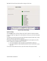
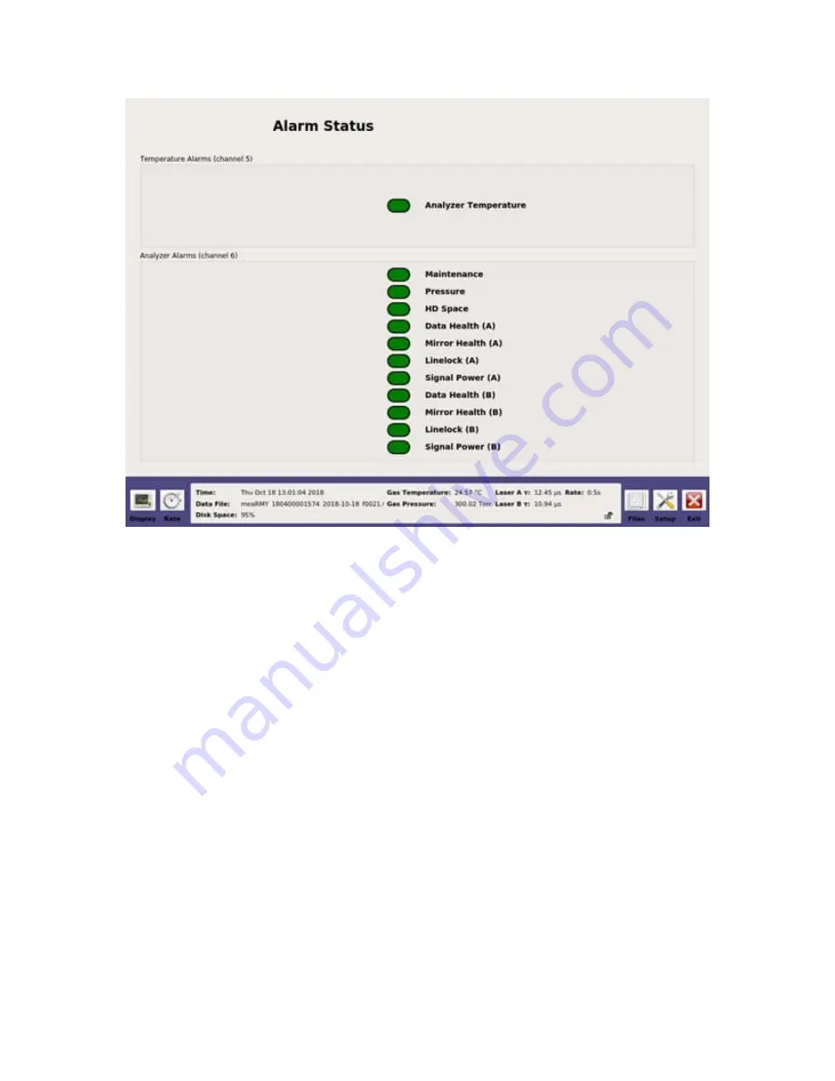
Figure 10: Alarm Status Display

Spectrum Display

Click the

Display

 button on the

User Interface Control Bar

 to switch to the

Spectrum Display

.

The top plot shows the voltage from the photo detector as the laser scans across the absorption
features.

The bottom plot shows the corresponding optical absorption displayed as black circles, and the
peak fit resulting from signal analysis as a blue line.

The analyzer is a dual-laser system. The

drop-down selector

 in the lower right portion of the

Spectrum Display

 lets you toggle between the two lasers:

Laser 1 (also referred to as laser A) displays CH

4

 and H

2

peaks (see Figure 11).

Laser 2 (also referred to as laser B) displays primarily H

2

O, but is also used for C

2

H

6

 (see

Figure 12).

The measured concentrations are shown in ppm at the bottom of the

Spectrum Display

.

Summary of Contents for GLA232 Series

Page 1: ... ABB MEASUREMENT ANALYTICS USER MANUAL User Manual ICOS GLA232 Series Methane Ethane Analyzer ...

Page 2: ...el are authorized to open the housing or service the laser WARNING Using this analyzer in a manner not specified by ABB may result in damage to the analyzer and render it unsafe to operate WARNING Only authorized persons may open the analyzer cover or perform internal maintenance Contact ABB for maintenance instructions and maintenance kits Make sure the analyzer is unplugged before working with t...

Page 3: ... 11 WEEE Directive 11 Laser Interlock 11 Electrical Hazards 12 Fire Hazards 12 3 Analyzer Overview 13 Performance Specifications 13 Ambient Humidity 13 Operating Temperature 13 Maximum Altitude 13 Power Requirements 13 Fuse Ratings 13 External Dimensions 13 Weight 13 Cell Volume 13 Resolution 13 Accuracy 14 Range 14 Data Sampling Rate 14 Standard Components 14 Power Connections 15 Emergency Shutdo...

Page 4: ... Daily Directory 30 Archive Directory 31 File Transfer Error Screen 32 Setup Mode 33 Time Files Tab 34 Laser Adjust Tab 36 Serial Logger Tab 37 Service Tab 38 Shutting Down the Analyzer 39 6 Maintenance 41 Daily Operation Checklist 41 Mirror Ringdown Time and Maintenance 41 Replace a Fuse 42 Clean the Rear Fan Filter 46 Appendix A About Gas Analyzers and Laser Absorption Spectroscopy 48 Convention...

Page 5: ...d software and to the contents of this document without obligation to notify any person or organization of such changes Every effort has been made to ensure that the information contained in this document is current and accurate Please contact ABB if you find any error in this document so we can make appropriate corrections Patent The ABB LGR ICOS GLA232 Series Methane Ethane Analyzer MEA or analy...

Page 6: ...prepared to provide the serial number or sales order number of the analyzer Text Formats and Warning Icons Text Formats This section describes text formats and warning icons used in this manual Italicized text is used for emphasis in text and also to emphasize the names of screens or text fields Bold text is used to show text that you type in fields and also button choices that you enter Warning I...

Page 7: ...s may be shipped in non pressurized aircraft Analyzers are fragile Do not drop or smash boxed analyzers Do not store analyzers outside in wet weather Do not stack boxes more than five high Analyzers may be safely stored at temperatures between 20 o C and 60 o C 4 o F and 140 o F NOTE Save the original shipping materials to use when returning the analyzer to ABB if factory service or repair is need...

Page 8: ...MATION 8 Table 2 Transportation and Storage Icon Descriptions Icon Meaning Store your analyzer in a sheltered dry area Do not let the box get wet Transport and store the analyzer box with the arrows on the box pointing up The analyzer is fragile Transport carefully Do not drop the box ...

Page 9: ...y information This manual describes the analyzer menu and data screens Even though this user manual provides additional information on the hardware components and their particular functions it is recommended to have qualified ABB service personnel resolve any issues with the analyzer For information on the ABB Ability Mobile Gas Leak Detection System MobileGuard refer to the ABB Ability Mobile Gas...

Page 10: ...nalyzer to operate with the case cover open may injure personnel Heavy Object WARNING Do not hand carry the analyzer To move the analyzer to its final mounting site it is recommended to use a wheeled table or have at least two people lift the analyzer When lifting the analyzer Use proper lifting techniques o Do not lift with your legs straight or from a forward bent position o Bend your knees and ...

Page 11: ... EMC EN61326 1 Title 21 Code of Federal Regulations chapter 1 sub chapter J WEEE Directive The analyzer is not subject to WEEE Directive 2002 96 EC Waste Electrical and Electronic Equipment or relevant national laws for example ElektroG in Germany The product must be disposed of at a specialized recycling facility Do not use municipal garbage collection points According to the WEEE directive 2002 ...

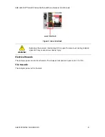
Page 12: ...re 1 Laser Interlock WARNING Bypassing the analyzer interlock switch to open the case cover during analyzer operation may cause serious bodily injury Electrical Hazards The analyzer poses no electrical hazards The analyzer components operate at 15 V DC Fire Hazards The analyzer poses no fire hazards ...

Page 13: ...uct Performance Specifications Ambient Humidity 0 to 95 non condensing Operating Temperature 5 50 o C 41 122 o F Maximum Altitude 3 000 meters 10 000 feet Power Requirements 220 W peak 200 W typical 11 5 15 V DC battery power Fuse Ratings 10 A instrument power 15 A pump power External Dimensions 56 cm L x 42 cm W x 18 cm H 22 in L x 16 5 in W x 7 in H Weight 26 kg 57 lb Cell Volume 355 cc cavity 5...

Page 14: ...alyzer components Verify these components arrived before you begin the setup The standard components include ABB LGR ICOS GLA232 Series Methane Ethane Analyzer Two analyzer power cords User Manual this document If you have not received all of the above components please contact ABB at 1 800 858 3847 North America or 1 418 877 2944 Worldwide or icos support ca abb com WARNING Connecting the analyze...

Page 15: ...d all of these components contact ABB at 1 800 858 3847 North America or 1 418 877 2944 Worldwide or icos support ca abb com Power Connections The power On Off switch is on the front panel of the analyzer see Figure 2 The DC power entry connectors are on the rear panel of the analyzer see Figure 3 The analyzer is typically powered by a vehicle battery If using a battery the battery voltage must be...

Page 16: ...ith MobileGuard ensure that no drive is currently active in the MobileGuard software 2 Flip the power switch on the front panel of the analyzer to OFF See Figure 2 3 If using the analyzer with MobileGuard disconnect both 11 5 15 V DC analyzer power plugs See Figure 4 Figure 4 One of the 11 5 15 V DC Power Plugs 4 Turn off the vehicle 5 Notify trained service personnel that the analyzer needs repai...

Page 17: ...zer s data logger Humidity Sensor 4 pin LEMO Connection for a humidity sensor to measure the temperature and percent humidity of the ambient air GPS Sensor TNC Connects a GPS antenna to the GPS receiver mounted on the lid of the analyzer Anemometer 9 pin D sub serial input Connects an anemometer or other serial devices to the analyzer s data logger Anemometer Power 12 V DC 3 A power barrel Coaxial...

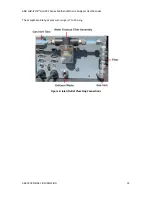
Page 18: ...ts directly into the analyzer but can optionally be connected to the waste port on the analyzer rear panel Gas Inlet Outlet Connections The gas inlet and optional outlet ports are located on the rear panel of the analyzer See Figure 6 for the gas inlet See Figure 3 for the gas outlet port EXHAUST WASTE NOTE Figure 6 displays a water dropout trap and additional 2 µm filter used in MobileGuard syste...

Page 19: ...ABB LGR ICOS GLA232 Series Methane Ethane Analyzer User Manual ABB PROPRIETARY INFORMATION 19 The acceptable inlet gas pressure range is 7 to 15 psig Figure 6 Inlet Outlet Plumbing Connections ...

Page 20: ... analyzer is designed to be powered by a vehicle battery IMPORTANT Do not start the vehicle while the analyzer is running Although the analyzer can run directly off the battery the voltage drops which occur when starting the vehicle result in rebooting the analyzer or leaving it in an indeterminate state For information on powering the analyzer using a vehicle battery refer to the MobileGuard Syst...

Page 21: ...ter This section describes two possible ways to do this via a remote VNC connection or by a local connection using a monitor keyboard and mouse connected to the analyzer Remote Connection If the analyzer is connected to a LAN and the IP address is known access the analyzer s operating system using a VNC connection password lgrvnc Local Connection Plug a VGA compatible monitor into the VGA port on ...

Page 22: ...re launches the Main Panel is displayed See Figure 7 This panel contains the User Interface Control Bar bottom of screen and Numeric Display main area Figure 7 Main Panel and User Interface Control Bar User Interface Control Bar Use the User Interface Control Bar to operate the analyzer Figure 8 User Interface Control Bar ...

Page 23: ... B τ Laser B 1680 nm ringdown time micro seconds µs Rate Sampling frequency Disk Space Remaining hard drive space Files Allows easy transfer of files onto USB storage devices Setup Accesses additional configuration and service menus Exit Exits the application and shuts down the analyzer Main Panel Displays Click the Display button to change the display in the Main Panel Clicking the Display button...

Page 24: ...button on the User Interface Control Bar to switch to the Alarm Status Display The alarm status for instrument parameters are color coded to indicate their current condition Green appears when the analyzer is functioning properly Yellow appears when data may not be reliable or when maintenance is required soon Red appears when immediate attention is required ...

Page 25: ...tom plot shows the corresponding optical absorption displayed as black circles and the peak fit resulting from signal analysis as a blue line The analyzer is a dual laser system The drop down selector in the lower right portion of the Spectrum Display lets you toggle between the two lasers Laser 1 also referred to as laser A displays CH4 and H2O peaks see Figure 11 Laser 2 also referred to as lase...

Page 26: ...ABB LGR ICOS GLA232 Series Methane Ethane Analyzer User Manual ABB PROPRIETARY INFORMATION 26 Figure 11 Laser 1 Spectrum Display Figure 12 Laser 2 Spectrum Display ...

Page 27: ...e chart with a continuous flow of CH4 and C2H6 A 10 point running average in black is shown going through the raw data shown in blue Click the drop down box in the lower right corner of either window to change displays of CH4 C2H6 and H2O concentrations and to adjust the number of significant figures The data are saved to the file indicated next to Data File at the left corner of the Parameter Win...

Page 28: ...peration a new data file is automatically created every 24 hours to keep data file sizes manageable Standard Data File Data files are written in text ASCII format and contain labeled columns displaying Time stamp of each aggregated data set set to Coordinated Universal Time UTC by default Time stamp of each raw analyzer measurement CH4 ppm H2O ppm C2H6 ppm Dry CH4 ppm Dry C2H6 ppm Cell pressure To...

Page 29: ...port on the front panel of the analyzer 3 Click the Mount USB button Figure 15 Figure 15 File Transfer Menu Local Hard Drive Left Pane and USB Flash Drive Right Pane 4 Transfer data files from the analyzer hard drive to a USB storage device by dragging and dropping the files from the hard drive pane to the USB device pane Use the left mouse button to highlight one or multiple files in the window T...

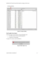
Page 30: ...es of directories Daily Archive Daily Directory The local hard drive Figure 15 creates a daily folder containing new data files for each day that the analyzer operates To access the data files for a specific date double click the folder Each file from that day is displayed in chronological order See Figure 16 Each file is a single zipped txt file using the following convention meaRMY_XXXXXXXXXXXX_...

Page 31: ...an archived folder containing zipped files organized by date see Figure 17 To access the archived files double click the Archive folder See Figure 15 Each file is a single zipped txt file using the following convention YYYY MM DD zip Each zipped file contains the data files for the day that the analyzer operated Examples of files in the archive directory are shown in Figure 17 ...

Page 32: ...ORMATION 32 Figure 17 Archive Directory File Transfer Error Screen The File Transfer Error screen shown in Figure 18 displays when The USB key does not have enough storage space The device is not recognized Try again with a correctly inserted USB device Figure 18 File Transfer Error ...

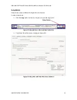
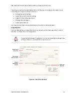
Page 33: ...etup mode accesses additional configurations and services To enter Setup mode 1 Click the Setup button on the User Interface Control Bar Figure 19 Figure 19 Setup Button on User Interface Control Bar 2 The default Time Files screen is displayed Figure 20 Figure 20 Setup Tabs with Time Files Screen Selected ...

Page 34: ...e settings Enable the laser offset adjustment Manage the serial logger Select service features Use these function tabs to make adjustments to the analyzer and its operation Time Files Tab The Time Files tab lets you adjust the time zone manually set the clock adjust the format of data files and adjust the serial configuration NOTE If using the MobileGuard application it is not recommended to chang...

Page 35: ... format of the data files The available timestamp formats are shown in Table 5 New file creation intervals when running continuously can be set by adjusting the value in the Output Interval minutes spinner control box Table 5 Available Time Stamp Formats Time Stamp Name Format Absolute Local American mm dd yyyy hh mm ss sss Absolute Local European dd mm yyyy hh mm ss sss Absolute GMT American mm d...

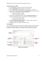
Page 36: ...b to manually adjust the laser s wavelength to compensate for any cumulative drift Figure 22 Laser adjustment may be required for the following reasons The laser s wavelength has drifted beyond the target range of the analyzer The analyzer is operated outside the recommended temperature range Figure 22 shows the offset between absorption peaks and target lines for laser A top plot and laser B bott...

Page 37: ...djust to the left 5 Adjust the Laser B voltage bottom plot using the Laser B Frequency Offset arrow buttons to shift the peaks until they are centered on their respective target lines o Up Arrow Peaks adjust to the right o Down Arrow Peaks adjust to the left 6 Uncheck the Disable Laser Frequency Lock box The software resumes automatic tracking and control of the laser wavelength 7 Click Close to e...

Page 38: ...ineers for updating changes made to the analyzer These settings determine the level of change that could affect measurement performance The alarm threshold levels are set based upon the last fixed setting Figure 24 Service Tab IMPORTANT Only qualified ABB field service engineers should reset the Tau Power or Counter values Improperly reset parameters may result in undiagnosed failures ...

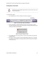
Page 39: ...r Exit Button 2 A pop up box appears in the Main Panel and prompts you to verify that you want to shut down the analyzer see Figure 26 This prevents unintentional button presses from causing interruption in data acquisition Figure 26 Analyzer Shutdown Prompt 3 Click the OK button to stop data acquisition close the current data file and display the shutdown screen 4 When the You may turn off the in...

Page 40: ...ABB LGR ICOS GLA232 Series Methane Ethane Analyzer User Manual ABB PROPRIETARY INFORMATION 40 Figure 27 Final Shutdown Screen ...

Page 41: ...splayed in the upper panel of the spectrum screen Any decrease in transmitted intensity may indicate dirty mirrors Log the analyzer pressure Any decrease in pressure could indicate an obstruction in the flow system An increase in pressure may indicate a leak in the system or a pump failure Every 3 6 days Check the laser offset and adjust if necessary Refer to the Laser Adjust Tab subsection Mirror...

Page 42: ...32 V DC blade ATO ATC color blue see Figure 29 Figure 28 10 A Fuse Figure 29 15 A Fuse To replace a fuse 1 If using the analyzer with MobileGuard ensure that no drive is currently active in the MobileGuard software 2 Flip the power switch on the front panel of the analyzer to OFF see Figure 2 IMPORTANT To prevent draining the vehicle battery do not turn off the vehicle before turning off the analy...

Page 43: ...3 7 If using the analyzer with MobileGuard remove the GPS receiver connections see Figure 30 o POWER two pin connector o ANTENNA TNC connector coaxial cable o PORT A serial port requires small flathead screwdriver Figure 30 GPS Receiver Connections 8 Remove the analyzer top cover see Figure 31 ...

Page 44: ...ABB LGR ICOS GLA232 Series Methane Ethane Analyzer User Manual ABB PROPRIETARY INFORMATION 44 Figure 31 Analyzer with Top Cover Removed 9 Locate the fuse See Figure 32 for locations ...

Page 45: ...o the GPS receiver 13 Carefully place the top cover on the analyzer and install the screws securing the cover to the analyzer 14 If using the analyzer with MobileGuard turn on the vehicle 15 If using the analyzer with MobileGuard re connect both 11 5 15 V DC analyzer power plugs See Figure 4 16 Flip the power switch on the front panel of the analyzer to ON see Figure 2 IMPORTANT To prevent drainin...

Page 46: ...sconnect both 11 5 15 V DC analyzer power plugs See Figure 4 4 Turn off the vehicle 5 Remove the fan filter cover located on the rear of the analyzer adjacent to the handle gently pull off the cover from the analyzer See Figure 33 Figure 33 Rear Fan 6 Remove the filter from its cover 7 Clean the filter with compressed air 8 If compressed air is insufficient clean the filter with water then make su...

Page 47: ...ABB LGR ICOS GLA232 Series Methane Ethane Analyzer User Manual ABB PROPRIETARY INFORMATION 47 IMPORTANT To prevent draining the vehicle battery do not turn on the analyzer before turning on the vehicle ...

Page 48: ...h may be expressed Where Iv is the transmitted intensity through the sample at frequency Io is the reference laser intensity prior to entering the cell S is the absorption line strength of the probed transition L is the optical path length of the laser beam through the sample 𝛘 is the mole fraction P is the gas pressure Φv is the line shape function of the transition at frequency 𝞾 In this case If...

Page 49: ...s Integrated Cavity Output Spectroscopy Off Axis ICOS uses a high finesse optical cavity as an absorption cell as shown in Figure 35 Unlike multi pass detectors typically limited to path lengths of less than 200 meters an Off Axis ICOS absorption cell effectively traps the laser photon so that on average photons make thousands of passes before leaving the cell As a result the effective optical pat...

Page 50: ...mined routinely by simply switching the laser off and measuring the necessary time for light to leave the cavity typically tens of microseconds As with conventional tunable laser absorption spectroscopy methods The wavelength of the laser is tuned over a selected absorption feature of the target species The measured absorption spectra are recorded and used to determine a quantitative measurement o...

Page 51: ...mart phones tablets and laptops Each of these devices uses Virtual Network Client VNC software to connect the analyzer through the router Follow the instructions below to install and set up VNC software on the device you are connecting to the analyzer Set up VNC Software on Android Devices 1 On the Android device go to Settings WiFi Connect to Wireless Network 2 Connect to the wireless SSID networ...

Page 52: ...ation 3 Select SSID 4 Enter the wireless password printed on the router sticker Figure 38 Every router has a different unique SSID number and wireless password Figure 38 Password Connection Screen 5 Select Connect Figure 38 6 A verification message appears showing that the Android device is connected to the router Figure 39 ...

Page 53: ...the 192 168 100 100 address does not connect use 192 168 100 101 8 Record the IP address of the Android device because it will be necessary to refer to it in Step 12 9 Install the VNC software by searching and installing from the Google Play store Search for Android vnc viewer and install the application by tapping on the Install button Figure 40 NOTE An Internet connection is required for this st...

Page 54: ...f the analyzer 192 168 100 100 or 192 168 100 101 that you recorded in Step 8 The IP address of the analyzer will be whichever address the Android device is not For example if the IP address of the Android device that was displayed in Step 8 is 192 168 100 101 then the IP address of the analyzer will be 192 168 100 100 13 In the Password field enter lgrvnc 14 Tap the Connect button to connect the ...

Page 55: ...ABB LGR ICOS GLA232 Series Methane Ethane Analyzer User Manual ABB PROPRIETARY INFORMATION 55 Figure 43 Analyzer Software Interface Display with Size Adjustment for Android Devices ...

Page 56: ...ork For example TP LINK D036 Figure 44 Figure 44 Network Connections Screen 4 The Enter Password screen appears Figure 45 In the Password field enter the wireless password on the router sticker Figure 36 5 Select Join Figure 45 Router Connection Screen 6 The Network Connections screen confirms that the iOS device is connected to the router Figure 46 Figure 46 Router Connection Confirmation Screen ...

Page 57: ...on Screen 9 Install the VNC software by searching and installing it from the App store o Mocha VNC Lite for iOS is the software used in this example Figure 48 o An Internet connection is required for this step NOTE Complete instructions for installing Mocha VNC Lite for iOS can be found online at http www mochasoft dk iphone_vnc_help2 help htm Figure 48 VNC Selection Screen 10 Open the application...

Page 58: ...igure 50 Mocha VNC Lite Configure Screen 12 Enter the analyzer s address in the VNC server address field 192 168 100 100 or 192 168 100 101 from Step 8 The IP address of the analyzer will be whichever address the iOS device is not For example if the IP address of the iOS device that was displayed in Step 8 is 192 168 100 101 then the IP address of the analyzer will be 192 168 100 100 13 In the VNC...

Page 59: ... displays the IP address Figure 51 Figure 51 Setup Configurations Screen 15 To connect the iOS device to the analyzer tap the IP Config you set up The analyzer software will display on the device Figure 52 The screen size is adjustable to fit the screen of the device Figure 52 Analyzer Software Interface Screen Size Adjustment for iOS Devices ...

Page 60: ... Wireless Router options 2 Locate the sticker on the router Figure 36 See Figure 37 for the location of the wireless router on the analyzer 3 Click on the Wireless Network Connections icon in the bottom left of the screen Figure 53 to open the Windows Wireless Networks dialog box Figure 54 Figure 53 Wireless Connections Icon Figure 54 Windows Wireless Networks ...

Page 61: ...e router sticker Example IBR200 xxxx to display the Connect to a Network dialog box Figure 55 5 In the Security key field enter the wireless password located on the router sticker Figure 36 6 Click OK Figure 55 Network Connections Security Screen 7 The Connection Status dialog box displays Figure 56 Figure 56 Current Connectivity Screen ...

Page 62: ...ection to make sure the device is connected through the wireless router by selecting the router Figure 57 Figure 57 Wireless Network Connection Screen 9 Verify the IP address of the Windows device a Right click on the TP LINK 775C network connection b Click Status Figure 58 Figure 58 Current Connectivity Screen ...

Page 63: ...ETARY INFORMATION 63 10 The Wireless Network Connection Status dialog box displays Figure 59 Figure 59 Wireless Network Connection Status Window 11 Click the Details button to display the Network Connection Details window Figure 60 Figure 60 Network Connection Details Window ...

Page 64: ...an be found online at http www realvnc com products vnc documentation 5 0 guides user Chapter1 html 14 Open the program by clicking the Connect button Figure 61 Figure 61 Real VNC Viewer Installation Screen 15 Enter the analyzer s address in the VNC server address field 192 168 100 100 or 192 168 100 101 from Figure 60 The IP address of the analyzer will be whichever address the Windows device is ...

Page 65: ...t Configuration Protocol DHCP request when the analyzer is initialized If the analyzer does not receive a reply the analyzer Disables the Ethernet port Does not attempt another DHCP request until the analyzer is restarted When both conditions are met the data directory can be accessed using a Windows computer on the same LAN Access Data Directory To access the data directory 1 Click Start Run and ...

Page 66: ...ollected to be written to the disk If a LAN is not available plug the analyzer into a standalone broadband router example Netgear Model RP614 to enable the analyzer to obtain a DHCP address from the router when the analyzer is started Then plug any Windows computer into the same broadband router to access the data directory A crossover Ethernet cable does NOT allow an external computer to access t...

Page 67: ...t prior notice With regard to purchase orders the agreed particulars shall prevail ABB does not accept any responsibility whatsoever for potential errors or possible lack of information in this document We reserve all rights in this document and in the subject matter and illustrations contained therein Any reproduction disclosure to third parties or utilization of its contents in whole or in parts...

Reviews: