background image


Page 93


© Copyright 2021 ABB. All rights reserved. 


16. Product Warranty


A.


Seller warrants to Customer only, that:


1.


As of the date title to Products passes, Seller will have the right to sell, transfer, and assign such Products and 
the title conveyed by Seller shall be good;


2.


During the warranty period stated in Sub

-

Article B below, Seller

s Manufactured Products (products 

manufactured by Seller), which have been paid for by Customer, will conform to industry standards and Seller

specifications and shall be free from material defects;


3.


With respect to Vendor items (items not manufactured by Seller), Seller warrants that such Vendor items, 
which have been paid for by Customer, will be free from material defects for a period of sixty (60) days 
commencing from the date of shipment from Seller

s facility.


B.


The Warranty Period listed below is applicable to Seller

s Manufactured Products furnished 

pursuant to this Agreement, commencing from date of shipment from Seller

s facility, unless 

otherwise agreed to in writing:


       *The Warranty Period for a repaired Product or part thereof is six (6) months or, the remainder of the unexpired term of the new      Product 

Warranty Period, whichever is longer.


C.


If, under normal and proper use during the applicable Warranty Period, a defect or nonconformity is 
identified  in  a  Product  and  Customer  notifies  Seller  in  writing  of  such  defect  or  nonconformity 
promptly after Customer discovers such defect or nonconformity, and follows Seller's instructions 
regarding return of defective or nonconforming Products, Seller shall, at its option attempt first to 
repair or replace such Product without charge at its facility or, if not feasible, provide a refund or 
credit  based  on  the  original  purchase  price  and  installation  charges  if  installed  by  Seller.  Where 
Seller has elected to repair a Seller

s Manufactured Product (other than Cable and Wire Products) 

which has been installed by Seller and Seller ascertains that the Product is not readily returnable for 
repair, Seller will repair the Product at Customer

s site.


With respect to Cable and Wire Products manufactured by Seller which Seller elects to repair but 
which are  not readily returnable  for repair, whether or not installed by Seller, Seller at its option, 
may repair the cable and Wire Products at Customer

s site.


D.


If  Seller  has  elected  to  repair  or  replace  a  defective  Product,  Customer  shall  have  the  option  of 
removing  and  reinstalling  or  having  Seller  remove  and  reinstall  the  defective  or  nonconforming 
Product. The cost of the removal and the reinstallation shall be borne by Customer. With respect to 
Cable and Wire Products, Customer has the further responsibility, at its expense, to make the Cable 
and Wire Products accessible for repair or replacement and to restore the site. Products returned 
for  repair  or  replacement  will  be  accepted  by  Seller  only  in  accordance  with  its  instructions  and 
procedures for such returns. 


Product Type


New Product


Repaired Product*


Central Office Power Equipment


24 Months


6 Months


Table 1: Warranty Period


Summary of Contents for GPS4827

Page 1: ...Page 1 Copyright 2021 ABB All rights reserved PRODUCT MANUAL GPS4827 Infinity Power System User s Guide Product Manual Ordering Code 850022019 Issue 1 January 2012 ...

Page 2: ... 2021 ABB All rights reserved Notice The information specifications and procedures in this manual are subject to change without notice ABB Power assumes no responsibility for any errors that may appear in this document ...

Page 3: ... 4 Rectifiers 17 NE050AC48ATEZ 17 5 AC Input Panels 21 Overview 21 6 Battery Connection Panels 23 7 DC Distribution Panels 25 Function 25 8 External Return Bars 31 Overview 31 9 Millennium II Controller Operation 35 Controller Connections 37 Installing Circuit Packs 38 Thermal Probes 42 USB Interface 43 Local Port 43 Wiring Alarm Outputs 43 Wiring Alarm and Control Inputs 46 Fuses 50 Front Panel D...

Page 4: ... Test Sequences 72 11 Circuit Boards 81 Overview 81 12 Specifications 83 Rectifier 85 13 Safety 87 Safety Statements 87 14 Maintenance and Replacement 89 Requirements 89 Rectifier Installation and Replacement Procedures 89 15 Troubleshooting Procedure 91 Preliminary 91 Troubleshooting Procedure 92 16 Product Warranty 93 17 Revision 95 ...

Page 5: ...ac input capability the GPS 4827 supports switching transmission and wireless applications in central office locations and environmentally controlled remote sites huts or vaults The main emphasis of this manual is to provide a general product description that will familiarize the user with the main components of the system and to provide guidelines for the basic maintenance of this Galaxy Power Sy...

Page 6: ...t other times this number is still available but for emergencies only Services provided include initiating the spare parts procurement process ordering documents product warranty administration and providing other product and service information For other customers worldwide the 800 number may be accessed after first dialing the Direct country code for the country where the call is originating or ...

Page 7: ...commercial utility or a standby ac power source and rectifies it to produce dc power for the using equipment The system s control and alarm functions interact with the rectifiers and the office In addition the system provides overcurrent protection and charge discharge and distribution facilities Battery reserve is connected in parallel and automatically provides a source of dc power if the commer...

Page 8: ...ies and to power the using equipment Controller provides the local and remote control monitoring and diagnostic functions required to administer the power system Batteries provide energy storage for an uninterrupted power feed to the using equipment during loss of ac input or rectifier failure DC Distribution Panel provides overcurrent protection connection points for the using equipment and bus b...

Page 9: ...attery connection panel rectifiers and a system controller Cabinets can also be ordered as rectifier only or distribution only cabinets Illustrations Figure 2 3 shows how supplemental cabinets may be added to grow the system for more distribution The rectifier output buses are interconnected to permit the cabinet to share current and ensure common voltage references for all system rectifiers The t...

Page 10: ...m Architecture 1800A Maximum per system SharedDC Power Battery String To Loads AC AC Ground Cabinet Ground SharedDC Power AC Battery String Battery String AC System CO Ground Cabinet Ground AC Ground Cabinet Ground AC Ground To Loads To Loads Controller Rectifier Battery Distribution Cabinet Rectifier Battery Distribution Cabinet Rectifier Battery Distribution Cabinet ...

Page 11: ... 11 Copyright 2021 ABB All rights reserved Figure 2 5 GPS4827 Six shelf cabinet with door removed Rectifier Shelves 3 6 or 9 AC Panel Circuit Breakers or Terminal strip Miscellaneous DC Distribution Panels ...

Page 12: ...Page 12 Copyright 2021 ABB All rights reserved This page intentionally left blank ...

Page 13: ...an interface to the cabinet control and alarm signals User Interface and Display The Millennium II s primary user interface is a backlit LCD front panel display that can be viewed in English or Spanish two rows of LEDs an array of pushbutton keys and a pair of test jacks Default Display The default display shows basic system status system voltage load current and plant state The controller returns...

Page 14: ...acks A pair of test jacks allows direct measurement of the dc bus sense voltage being monitored by the controller Pushbutton Keys A group of pushbutton keys below the backlit LCD display provides the primary user interface with the controller These keys are used singly or in combination to navigate through the controller s menus The following is a general description of the pushbutton keys ESCAPE ...

Page 15: ...el A rubber flap can be opened to access the local port connector The DB 9 local port connector supports standard RS232 serial communication Refer to the Galaxy Millennium II Controller product manual for additional details on port configuration and isolation ...

Page 16: ...ler product manual Select Code 167 792 180 is furnished with every GPS 4827 Refer to this manual for information regarding configuration and operation RPM System Product Manual Refer to the Galaxy Remote Peripheral Monitoring System product manual Select Code 167 790 063 for additional information regarding module operation ...

Page 17: ...or adjustments to potentiometers are necessary The NE050AC48ATEZ rectifiers are UL Recognized for both the U S and Canada comply with UL1950 Information Technology Equipment and meet EN60950 requirements Front Panel Display Status Indicators Three LEDs on the rectifier s faceplate indicate the rectifier s condition The Norm LED is green and is lit when the rectifier has AC input present and is wor...

Page 18: ...start Upon shutdown the rectifier will attempt to restart The rectifier will also accept a restart command from the controller for a remote restart The rectifier will attempt to restart three times before issuing a rectifier fail alarm to the controller Fan Alarm and Control The rectifier contains a cooling fan The fan s speed which is based on ambient temperature and output power level is lowered...

Page 19: ...alarm signals ac input and dc output are all connectorized for easy installation and maintenance System connections are made when the rectifier is plugged into the shelf No additional connections are required Forced Load Sharing Internal rectifier circuitry will allow rectifiers to share load in the event communication to the controller is lost or the controller malfunctions ...

Page 20: ...Page 20 Copyright 2021 ABB All rights reserved This page intentionally left blank ...

Page 21: ...ingle phase either 2 hot leads or 1 hot lead and neutral input ac service Some options provide circuit breakers to protect the conductors providing ac service to the individual rectifiers Other options provide a terminal strip and the conductors are protected by circuit breakers located in the building s ac service panel Note See AC input table in the Specification section for recommended conduit ...

Page 22: ...reserved CB1 CB2 CB3 CB4 CB5 CB6 CB7 CB8 CB9 CB10 CB11 CB12 G11 G12 G21 G22 G31 G32 G41 G42 G51 G52 G61 G62 G13 G14 G23 G24 G33 G34 G43 G44 G53 G54 G63 G64 Figure 5 3 AC Input circuit breaker panel Figure 5 3 AC Input circuit breaker panel ...

Page 23: ...formation The optional panels may include a low voltage battery disconnect reconnect LVBD R contactor When equipped with a LVBD R a contactor control card provides local manual control of the contactor Illustrations The optional LVBD R battery connection panel shown in Figures 6 1 Note Battery connection panels are blue dc distribution panels are white Figure 6 1 H5694827 G39 ED83143 31 G36 Option...

Page 24: ...Page 24 Copyright 2021 ABB All rights reserved This page intentionally left blank ...

Page 25: ... operates or a circuit breaker trips a red LED on the alarm card lights the cabinet alarm lights and the alarm is transmitted to the controller Distribution panels are also available with contactors to provide low voltage load disconnect Illustrations The dc distribution panels are illustrated in Figures 7 1 through 7 11 Note DC distribution panels are white battery connection panels are blue Figu...

Page 26: ...ht 2021 ABB All rights reserved Figure 7 3 H569 4827 G48 ED83143 31 G5 DC Distribution Panel Figure 7 4 H569 4827 G96 ED83143 31 G15 DC Distribution Panel Figure 7 5 H569 4827 G52 ED83143 31 G53 DC Distribution Panel ...

Page 27: ...21 ABB All rights reserved Figure 7 6 H569 4827 G53 ED83143 31 G55 DC Distribution Panel Figure 7 7 H569 4827 G60 61 65 66 ED83143 31 G71 DC Distribution Panel Figure 7 8 H569 4827 G67 ED83143 31 G22 DC Distribution Panel ...

Page 28: ...ll rights reserved Figure 7 9 H569 4827 G68 ED83143 31 G21 DC Distribution Panel Figure 7 10 H569 4827 G97 G98 ED83143 31 G17 DC Distribution Panel Alarm Terminal Card G97 6 REF 152mm G98 9 REF 229mm Connects to Charge Return Bus ...

Page 29: ...ution Panel Shut Motoring Connection Points to RPMs TPL C Fuse Head Furnished with Block Order 408472322 TPL B Fuse Block Head for 70A 250A Fuses Connects to Charge Return Bus 6 REF 152mm Alarm Terminal Card 300A Shunt in back of panel per Position 5 Large TPL B Fuse Positions Connects to Charge return Bus Maximum Panel Capacity 1125A 800A with LVLD 9 REF 229mm ...

Page 30: ...Page 30 Copyright 2021 ABB All rights reserved This page intentionally left blank ...

Page 31: ...e kits are alternatives to the standard internal return buses These kits allow for modular growth of the bars from bay to bay and offer additional cable landings Illustrations The dc distribution panels are illustrated in Figures 9 1 through 9 11 Figure 8 1 Standard Architecture 600mm External Return Bus Kit CC848805160 for distributed architecture cabinets ...

Page 32: ...2021 ABB All rights reserved TBD Standard Bay TBD Wide Bay Modular Distribution Bay Overhead Buses TBD Modular Rectifier Bay Overhead Bus Figure 8 2 Horizontal Rectifier Standard and Wide Distribution Bay bus bar system ...

Page 33: ...21 ABB All rights reserved TBD Modular Distribution Wide Bay Overhead Bus Field Option A Field Option B TBD Rectifier Bay Overhead Bus Figure 8 3 Vertical rectifier standard and wide distribution bay return bus bar systems ...

Page 34: ...Page 34 Copyright 2021 ABB All rights reserved This page intentionally left blank ...

Page 35: ... bars or turning up the plant rectifiers Precautions Observe ESD protection while installing circuit packs Wear grounded antistatic wrist straps when handling all circuit packs The wrist strap must contact the skin and is not to be worn over clothing Never hand a circuit pack from a grounded to a non grounded person or vice versa Safety Action Verified Always consider personal safety before beginn...

Page 36: ...als Item Verified Wire cutters and strippers 18 to 22 AWG wire Jewelers screwdriver Flat and Phillips Small needle nose pliers Digital meter 0 02 Screw Drivers flat blade and Phillips ESD wrist strap Wire wrap tool or Amp alarm punch down tool Figure 9 1 Millennium II ...

Page 37: ...eptacle for isolated RS485 system component monitoring and control of rectifiers converters low voltage disconnect contactors and bay level alarm inputs Serial Rectifier bus P13 Factory test connector not used in the field P14 Connectorized interface for future smaller serial format LCD P15 Connectorized interface for future smaller serial format LCD P201 Connectorized interface for optional Modem...

Page 38: ...6 screws 3 Connect the 848091798 cable assembly between the BSM J100 plug and P201on the MCR1 board 4 Note This step may be performed at a later time Install phone line wiring from Connect the existing telephone cable to the RJ11 connector at the top of the board OR Connect Tip Ring conductors to TB1 at the top of the board NOTE Tip is TB1 pin 1 Pin closest to the RJ11 connector and Ring is Pin 3 ...

Page 39: ...SW pack inside the 847950938 insulator 3 Plug BSW pack into the P205 connector on the BSJ intelligent controller board 4 Secure the BSW board to the standoffs with two 900562208 screws NOTE To install the Data Switch Extension board please see the User s Guide for Millennium II Controller Advanced Features manual Step Action 1 In the upper right hand corner of the MCR1 board find the alarm board a...

Page 40: ...ed to connect to the network is variable this cable must be supplied by the user 1 At the controller connect one end of the network interface cable to P2 This connector is located at the bottom center of the MCR1 board and immediately below the MCR2 board 2 Connect the other end to an IEEE 802 3 compatible network 3 Configure the Gateway for the network by contacting the customer s network adminis...

Page 41: ... the bus wire are NOT polarity sensitive Connections of the bus wire are NOT Polarity Sensitive there are 2 IN and 2 OUT connections Either one may be used 5 Locate the control unit This is the half with circuitry on it 6 In the lower right hand side of the control unit inside are two rotary switches Set SW 1 LO to 1 The module will be recognized as 01 by the controller Other modules added cannot ...

Page 42: ...hermal probe inputs The type of probe used determines where it is connected on the controller Detailed thermal probe and battery management information may be found in the User s Guide for Millennium II Controller Advanced Features manual 1 The following table shows the type of probe and connector location on the Millennium Type of Probe Ordering Code Controller Connection Location 10 30K P3 210E ...

Page 43: ...tion Pin Number Signal Name Pin Number Signal Name Pin Number Signal Name 1 PCRAO 33 MJFR 65 FAN 2 PCRAC 34 MNFR 66 AMN 3 PCRAR 35 MNFC 67 TFLT 4 PCRVR 36 MNFO 68 TBST 5 PCRVC 37 BDO 69 TRTN 6 PCRVO 38 BDC 70 PBTR 7 PCREO 39 BDR 71 PBT 8 PCREC 40 ACFR 72 OS Table 9 B Controller Alarm Descriptions and Pin Numbers Form C Alarm Contact Ratings 60Vdc 0 3A Conductor Size for terminating on Alarm board ...

Page 44: ...PMJVO 50 UR1C 82 TBD now general I O 1 19 PMNAO 51 UR1R 83 USR1PRESENT BTP now general I O 2 20 PMNAC 52 CTLRR 84 LVD1 21 PMNAR 53 CTLRC 85 TR3 22 PMNVR 54 CTLRO 86 23 PMNVC 55 UR2O 87 4 20mA in 24 PMNVO 56 UR2C 88 4 20mA Rtn 25 5V 57 UR2R 89 USR3PRESETN BTPFLT now general I O 3 26 58 UR3R Now VLVR 90 USR3DETECT BTMJ 27 59 UR3C Now VLVC 91 0 5V in 28 PMNER 60 UR3O Now VLVO 92 0 5V Rtn 29 PMNEC 61 ...

Page 45: ...r Audio 10 PMJAR 11 PMJAC 12 PMJAO Power Major External 13 PMJEO 14 PMJEC 15 PMJER Power Major Visual 16 PMJVR 17 PMJVC 18 PMJVO Power Minor Audio 19 PMNAO 20 PMNAC 21 PMNAR Power Minor Visual 22 PMNVR 23 PMNVC 24 PMNVO Power Minor External 28 PMNER 29 PMNEC 30 PMNEO Major Fuse 31 MJFO 32 MJFC 33 MJFR Minor Fuse 34 MNFR 35 MNFC 36 MNFO Battery On Discharge 37 BDO 38 BDC 39 BDR ...

Page 46: ...2 Disconnect State Detect 61 LVD2 Fuse Alarm Major 63 FAJ Fuse Alarm Minor 65 FAN Auxiliary Alarm Major 64 AMJ Auxiliary Alarm Minor 66 AMN Timer Float Control 67 TFLT Timer Boost Control 68 TBST Plant Battery Test 71 PBT Open String Detect 72 OS Transfer Rectifier 1 73 TR1 Wiring Alarm and Control Inputs In a standard Galaxy Power System configuration plant level alarms are sent to the controller...

Page 47: ...Power Off 81 RBRPO General Purpose Input 1 82 IN 1 BTP or General Purpose Input 2 83 IN 2 BTP Low Voltage 1 Disconnect State Detect 84 LVD1 Transfer Rectifier 3 85 TR3 General Purpose 4 20mA Measuring 87 4 20mA Circuit General Purpose 4 20mA Measuring Circuit RTN 88 4 20mAR BTPFLT or Generic Input 3 89 IN 3 BTPFLT Low Voltage 3 Disconnect State Detect Also Battery Thermal Protect Major 90 LVD3 BTM...

Page 48: ...o allow Galaxy to monitor another power device and provide alarms for it An Aux Minor Alarm is generated when battery potential is received LVD1 BSL 84 Low Voltage Disconnect Active A battery potential input is required which must use an external 1K ohm 2W current limiting resistor at the source if not using standard ABB Power LVD circuit boards or controller This circuit is used to inform Galaxy ...

Page 49: ...mperature be monitored If either of these features is to be configured in Galaxy software a battery temperature input must be connected to P3 temperature probe connector on the Controller board Three optional cables are used to connect to various battery arrangements Refer to User s Guide for Millennium II Controller Advanced Features manual for additional information on these features Alarm Batte...

Page 50: ... 95 96 DG Discharge Ground Plant ground return source for user alarm systems Fuses Two Fuses located on the MCR1 board provide protection for the controller input power and Alarm Battery Supply used to power alarm panels or other devices requiring the power system voltage at no more than 1 3A FUSE Description Fuse Size F1 Controller Input Power 3A F2 Alarm Battery Supply ABS 1 3A Figure 9 4 Millen...

Page 51: ...patible to both existing Millennium LCD assemblies L51 and L50 shown in Figure 4 5 It is also compatible with the enhanced L52 LCD display assembly see figure 4 6 specifically developed for the Millennium II This new display assembly is compatible to existing GPS cabinet doors and is functionally backwards compatible to the Millennium It looks very similar to the L51 option LCD assembly but the L5...

Page 52: ...ected The controller measures this voltage to regulate the system bus voltage as well as display it as the battery plant bus voltage The value of this voltage is used for many other controller related features Serial PC Port A ground referenced RS 232 local port is provided at the front of the display to allow easy connection to a personal computer or terminal using ANSI T1 317 object oriented com...

Page 53: ...udible on PCR Audible on PMJ Audible on PMN For L50 L52 Displays Press the or keys and hold until the display changes it s contrast setting Once the desired setting is reached re lease the button For L51 Displays Using a small flat head jeweler s screwdriver insert it into the small opening at the top of the display assembly above the UP arrow Turn clockwise or counter clockwise until the display ...

Page 54: ...02 7 0 Modem Aux Local Gateway USB IRDA Port Setting Configuration Remote Access ENABLED DISABLED SW202 6 0 Enhanced Security Mode See table 4 H for features affected ENABLED DISABLED SW202 5 1 Auxiliary Port Configuration RS 232 RS 485 SW202 4 1 Remote Rectifier in Standby ENABLED DISABLED SW202 3 0 Boost Mode ENABLED DISABLED SW202 2 1 Reserved for Future Use ENABLED DISABLED SW202 1 1 Reserved ...

Page 55: ...fier Float Set Point Change Rectifier Boost Set Point Change Rectifier Boost Current Limit Change Converter Voltage Set Point Change Converter Low Voltage Disconnect Threshold Change Converter Low Voltage Reconnect Threshold Enable or disable Converter Low Voltage Disconnect feature Change Converter Status to Standby Vacant status is prohibited The change to On status is allowed Change Battery Hig...

Page 56: ...5 26 8 48V Float 50 00 60 00 53 6 48V Boost 52 00 60 00 53 6 Rectifier On Threshold ROT 24V 20 00 25 00 22 00 48V 40 00 51 00 44 00 Table 9 I Voltage Threshold Ranges and Default Values Symbol Default Designation Default Severity Default LED Default Relay AAC ACO Active RO None None ABS Alarm Battery Supply Fuse Major CTLR CTLR AMJ Auxiliary Major Major None None AMN Auxiliary Minor Minor None Non...

Page 57: ... Contactor 2 Failed Major BAT None CNF3 Contactor 3 Failed Major BAT None CNO1 Contactor 1 Open Major BAT None CNO2 Contactor 2 Open Major BAT None CNO3 Contactor 3 Open Major BAT None COF Queue Overflow Warning None None COR Number Did Not Respond Warning None None CPA Circuit Pack Fail Major CTLR CTLR CRA Controller Fail Major CTLR CTLR DID Rectifier ID Conflict Major RECT None EMD Energy Manage...

Page 58: ...OSA Open String Minor BAT None PFD Password At Default Warning None None PGI Program Line Invalid Major None None PHT Processor Halt RO None None POR Number Did Not Respond Warning None None RLS1 Redundancy Loss Ninor RECT None RPI Rectifier Plant Inconsistency Warning None None RTL Reserve Time Low Minor BAT None SNC Shunt Not Configured Warning None None STF Self Test Failed Minor CTLR CTLR TPA ...

Page 59: ...down Minor RECT None HPA Half Power Minor RECT None LCA Low Current Alarm Minor RECT None LSF Load Share Fuse Minor RECT None MACF Multiple AC Fail Major AC ACF MAN Manual Off Minor RECT None MFA Multiple Rectifier Fail Major RECT RFA MMAN Multiple MAN Alarm Major RECT None PHA Phase Or Low Output Minor AC None RIC Rectifier Incomplete Config Warning None None RFA Rectifier Fail Minor RECT RFA Fig...

Page 60: ...on volatile memory Audible Alarm Cutoff State Toggle Only shown if an alarm is active Plant Mode Default Float Screen information is updated approximately every two seconds The front panel display offers a series of menus that allow the user to Configure Control View Status View History View Statistics Perform Diagnostics These menu operations are accomplished by navigating through different scree...

Page 61: ...Page 61 Copyright 2021 ABB All rights reserved Controller Display Menu Maps Configuration Menu Map ...

Page 62: ...Page 62 Copyright 2021 ABB All rights reserved Control and Operations Menu Map ...

Page 63: ...Page 63 Copyright 2021 ABB All rights reserved Status Menu Map ...

Page 64: ...Page 64 Copyright 2021 ABB All rights reserved History Menu Map Statistics Menu Map ...

Page 65: ... This field allows you to select one of the following date formats MM DD YY DD MM YY YY MM DD MM DD YYYY DD MM YYYY YYYY MM DD Use the or key to select the desired format and press ENTER to save the change Month Use this field to change the month the possible value is from 1 to 12 Day Use this field to change the day of the month the possible value is from 1 to 31 Year Use this field to change the...

Page 66: ... A maximum of two shunts of the same amperage can be connected through P6 on the BSH A shunt type of LOAD means that a load shunt located between load and plant bus bars is connected The load current displayed on the front panel is the sum of the two shunt currents A shunt type of BATTERY means that a battery shunt located between the batteries and plant bus bars is connected The load current disp...

Page 67: ...an adjustment in the plant rather than due to a failure This alarm allows the High Voltage HV shutdown threshold to be raised slightly thus reducing the number of nuisance shutdowns without decreasing the plant reliability Move the cursor to the fields and use the or key to adjust the High Voltage shut down alarm for FLOAT mode to the desired level normally less than the HV threshold Press ENTER t...

Page 68: ...tery types used in reserve time prediction and enhanced battery test features Move the cursor to the field and use the or key to adjust the threshold value Press ENTER to save the change Strings The configuration of this field selects the number of battery strings in the system This parameter is used in reserve time prediction and enhanced battery test features Move the cursor to the field and use...

Page 69: ...Comp This feature allows the system to compensate for high temperatures Volt StepDown Battery step temperature can be set from 113 185F At this temperature the system voltage is reduced by 0 17 X of cells string High Comp Limit This sets the maximum temperature for which thermal compensation is active Decrease This sets the slope mV degC for high temperature compensation NominalTemp This field set...

Page 70: ...hosen here For standard GPS configurations using BIC cards Contactor 1 is wired to and controls all BATTERY contactors in the plant Contactors 2 and 3 are wired to and control only LOAD contactors To toggle between the various contactor types move the cursor to one of the fields and use the or key to select the desired type Press ENTER to save the change Disconnect This setting configures the plan...

Page 71: ...al Voltmeter DVM with dc accuracy of at least 0 05 Short length of wire or clip lead for jumper Jeweler s screwdriver Follow these steps to test plant alarms when installing the Galaxy Millennium Controller in a new plant In a new installation begin the sequence with the rectifiers running with a dummy load on the plant bus bar For these tests it is assumed that All rectifiers are functioning prop...

Page 72: ...ont panel of the controller are functioning properly No alarms are generated from this test Step Action 1 From the Default Screen press the Menu button for the Main Menu 2 Using the Up Down Arrows Scroll to Control Operations and press Enter 3 Select Start Lamp Test and press Enter 4 Press Enter again to start the test or Escape to return to the menus 5 Observations LCD Refreshes Front Panel LEDs ...

Page 73: ...LTAGE Use the Arrows and UP DOWN keys to calibrate the system voltage Press ENTER to save NOTE The controller will not allow changes greater than 0 5V of the displayed voltage 4 Press the ESCAPE key until the default screen is displayed Verify that the plant voltage reading now agrees with the calibrated DVM NOTE The DVM reading will be the one to change since Rectifier Manager will adjust rectifi...

Page 74: ...E This operation is performed and verified ONLY if plant load is constant during the calibration procedure Observation Displayed System load changes to new value High Float Voltage Alarm New Installations only Step Action for Testing the High Float Voltage Alarm NOTE Clear all controller alarms for this test NOTE The high voltage alarm test is completed by raising the plant voltage above the thres...

Page 75: ...em voltage to make itactive 1 Using the Float Settings Menu Screens select Set Point and note the value 2 Using the Voltage Alarms Menu Screens note the High Float Alarm threshold value 3 Use the Arrows and UP DOWN keys to change the High Float Alarm Threshold to 0 1V below the System Voltage Press ENTER to save 4 Observe Power Minor alarm PMN is generated RECT and MIN LEDs are illuminated 5 Using...

Page 76: ...tifier Fail Alarm to the controller If there is a sufficient interval between restart and a subsequent shutdown the rectifier resets its restart counter The controller initiates a restart signal a few seconds after the first RFA HO alarm is received After the second RFA HO is received the controller waits 5 minutes before sending one additional restart signal 1 Verify the Auto Restart is enabled f...

Page 77: ...the ALM LED on the rectifier is not lit Upon the fourth shutdown the rectifiers ALM LED lights and the rectifier s display indicates HO Any external RFA office alarm has occurred The controller will wait 5 6 minutes and issue one final restart signal initiating the final sequence of shutdown and restart events before the rectifier locks out requiring personnel intervention Prior to this occurring ...

Page 78: ...nated 5 Turn on all rectifiers 6 Controller Observations PMJ Alarm retires BD and MAJ LEDs are extinguished System Voltage is normal Rectifier Fail Alarm The RFA alarm was observed during the High Voltage Shutdown Test so no separate test is required Major Fuse Alarm Major Fuse Alarm may be tested by placing a blown fuse in the alarm fuse position ofany distribution fuse position in the plant or b...

Page 79: ...feature is useful when there is a need to remove unnecessary historical data from the controller An example might be after installation and testing and the controller is ready for operation There may be history that is of no use to the customer Also since the history log has a finite number of entries user can save the history using a PC and then clear the logs Step Action 1 From the Default Scree...

Page 80: ...Page 80 Copyright 2021 ABB All rights reserved This page intentionally left blank ...

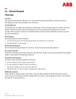
Page 81: ...aults occur on the panel provide alarm data to the controller Alarm Terminal Boards Alarm terminal boards combine the functions of alarm boards and terminal boards BLJ Terminal Board The BLJ terminal board is located inside the cabinet door The BLJ is the termination point for all signal cables in each cabinet and between cabinets Contactor Control Board Contactor control boards provide four funct...

Page 82: ...Page 82 Copyright 2021 ABB All rights reserved This page intentionally left blank ...

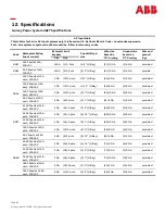
Page 83: ...ed 12 AC Feeds at 15A each 200 VAC 20A 12 2 pole 4 1 1 Bay 24 10 GA 4 8 GA provided 6 AC Feeds at 30A each 200 VAC 40A 6 2 pole 2 1 1 Bay 12 8 GA 2 8 GA provided G027 24 AC Feeds at 15A each 200 VAC 20A 24 2 pole 3 2 1 Bay 48 8 GA 3 8 GA provided 24 AC Feeds at 15A each 200 VAC 20A 24 2 pole 6 1 5 1 Bay 48 10 GA 6 8 GA provided 24 AC Feeds at 15A each 200 VAC 20A 24 2 pole 8 1 1 Bay 48 10 GA 8 8 G...

Page 84: ...Environmental Operating AmbientTemperature 0 C to 45 C Altitude 50 to 4000 meters Note For altitudes between 1500 and 4000 meters derate the maximum temperature by 0 656 C per 100 meters Humidity 5 to 95 non condensing Radiated and Conducted Emissions FCC Part 15 EN55022 CISPR22 EN55024 Level A GR1089 Electromagnetic Immunity Complies with GR1089 Earthquake Rating Zone 4 upper floors Standards Com...

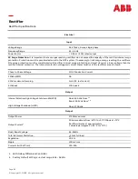
Page 85: ...coordinated with rectifier internal surge protection and must clamp at a lower voltage than the rectifier internal protection The internal protection voltage and current characteristics of the rectifiers are as follows Output Internal Selective High Voltage Shutdown ISHVSD High Voltage Shutdown HVSD Float 56 0Vdc Nom 1 2 Boost 58 5Vdc Nom 1 2 Float 57 00Vdc Output Output Power 2726W maximum Output...

Page 86: ...NE050AC48ATEZ 52Vdc 40A52Vdc 50A 54 5Vdc 40A 54 5Vdc 50A Per rectifier 109W 372 BTU hr 137W 463 BTU hr 115W 392 BTU hr 143W 488 BTU hr Storage Relative Humidity 5 to 90 Standards Compliance Safety Standard EN 60950 IEC950 Certification Marks UL CE Rectifiers are individually UL Recognized and or CSA Certified to UL1950 and CSA C22 2 No 234 950 Rectifiersare also approved to IEC 950 EN60950 by an E...

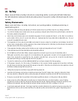
Page 87: ... be used to terminate Listed field wired conductors where required For all installations the appropriate connector is to be applied only to the correct size conductor as specified by the connector manufacturer using only the connector manufacturer s recommended tooling or tooling approved for that connector The shelf in combination with the NE050AC48ATEZ has not been evaluated for hot swapping If ...

Page 88: ... grounding techniques that are equally successful Adhere to a commonly accepted and consistent grounding approach to ensure personnelsafety network protection and proper equipment operation Multiple low impedance paths to Earth ground are essential The equipment and subassembly ports are suitable for connection to intra building or unexposed wiring or cabling The equipment and subassembly portscan...

Page 89: ...ep Action 1 Locate and turn off the ac service to the rectifier positionthat is being installed or replaced Note Do not turn off ac service to the entire system only to the rectifier position that is being installed or replaced 2 Caution Rear portion of the rectifier that is in operation may be HOT to the touch Use appropriate precautions 3 This step is for replacement only For a new installation ...

Page 90: ...Page 90 Copyright 2021 ABB All rights reserved This page intentionally left blank ...

Page 91: ...ecessary in order to troubleshoot the GPS 4827 Calibrated digital voltmeter DVM 0 05 accuracy on dc scale ESD wrist strap 15 Troubleshooting Procedure Preliminary Introduction This section provides information needed in preparation for locating and interpreting visual indicators to help identify problems When replacing a part does not correct the problem or visual indicators do not identify a defe...

Page 92: ...tus For most problems one or more alarm and status LEDs will be illuminated Depending on the controller type the following will be displayed system voltage system current system mode system number of alarm warnings If the screen is blank but alarm and status LEDs are illuminated call technical support If the entire panel is blank check the controller fuses Verify that the controller is getting pow...

Page 93: ...s such defect or nonconformity and follows Seller s instructions regarding return of defective or nonconforming Products Seller shall at its option attempt first to repair or replace such Product without charge at its facility or if not feasible provide a refund or credit based on the original purchase price and installation charges if installed by Seller Where Seller has elected to repair a Selle...

Page 94: ... or abuse improper wiring repairing splicing alteration installation storage or maintenance use in a manner not in accordance with Seller s or Vendor s specifications or operating instructions or failure of Customer to apply previously applicable Seller modifications and corrections In addition Seller makes no warranty with respect to Products which have had their serial numbers or month and year ...

Page 95: ...Page 95 Copyright 2021 ABB All rights reserved 17 Revision Rev Description Date Dept Init 1 2 Updated as per template 10 08 2021 ...

Page 96: ...t any responsibility whatsoever for potential errors or possible lack of information in this document We reserve all rights in this document and in the subject matter and illustrations contained therein Any reproduction disclosure to third parties or utilization of its contents in whole or in parts is forbidden without prior written consent of ABB Copyright 2021 ABB All rights reserved ABB 601 Shi...

Reviews: