background image

15

G EN ER A L  D E S C R I P T I O N

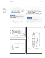
4.4.2 Control relay

The standard ABB control cabinet supplied with  
the GridShield

®

 recloser includes a relay-agnostic 

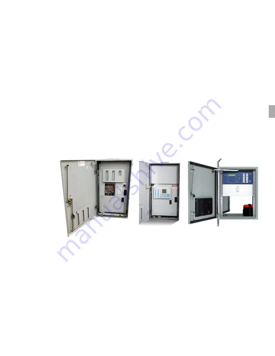
control cabinet (figure 12). This cabinet comes with 
the option of Beckwith M-7679, RER620 or RER615 
(for 3-phase operation only). Optionally,  
a dedicated RER620 control cabinet is available 
with 24-pin option (figure 13). This controller 
integrates most of the normal recloser control 
functions into a single device, providing a wide 
range of protection, control, metering, automation 
and remote control options. Additionally,  
a complete SEL-651R control cabinet is an option 
(figure 14). For details on programming, operating 
and testing of the control, please refer to its 
respective instruction manual. For details on the 
overall control circuit, refer to the specific wiring 
diagrams supplied with the recloser. 


14 


13 


12 24-/32-/42-pin relay-
agnostic control cabinet

13 24-pin RER620 
control cabinet

14 SEL-651R 
control cabinet

4.4.3 Control cable

The ABB GridShield recloser is equipped with a 24-/ 
42-pin control cable, specifically designed by ABB. 
We strongly advise using the ABB control cable to 
ensure precise measurement of current and voltage 
by the embedded sensors on the poles and to 
optimize the overall performance of the recloser.  
If you require a spare control cable or need to replace 
your current cable, please reach out to your ABB 
sales representative.


12 

04

Summary of Contents for GridShield 3P

Page 1: ... DISTRIBUTION SOLUTIONS GridShield 3P 3SP recloser Installation operations and maintenance manual ...

Page 2: ......

Page 3: ...sing 16 5 2 Opening 16 5 3 Mechanical opening 16 6 Standard production tests factory only 17 7 Operational checks prior to installation 18 7 1 Electrical close 18 7 2 Electrical trip 18 7 3 Programmable pushbuttons 19 7 4 Vacuum test procedure 19 8 Installation 20 8 1 Mounting 20 8 1 1 Pole mounting 20 8 1 2 Substation mounting 23 8 1 3 No frame 25 8 2 Grounding 25 8 2 1 Pole mounted recloser grou...

Page 4: ... GridShield 3P 3SP recloser ...

Page 5: ...us programs etc to protect the products network system and interfaces against security breaches unauthorized access interference intrusion data leakage or theft Notice ABB conducts functionality testing and releases updates for the products However it is the ultimate responsibility of the system product owner to ensure that any product or system updates including code changes configuration file ch...

Page 6: ...safe working practices Furthermore individuals working in or around this equipment must exercise common sense and good judgment to recognize potential hazards for themselves and others in the vicinity These instructions are specifically designed for fully qualified personnel and should not be considered a substitute for adequate training experience and supervision If any clarification or additiona...

Page 7: ...vable service methods whether recommended by ABB or not Furthermore ABB cannot anticipate or investigate every potential hazard resulting from all conceivable service methods Therefore anyone using service procedures or tools regardless of ABB s recommendations must ensure that both personal safety and equipment safety are not compromised by the selected service method or tools All information con...

Page 8: ... Additionally as improvements are made to parts and assemblies the appearance of some parts may differ from the illustrations However their functionality will remain equivalent 2 3 GridShield3P 3SP recloser introduction The GridShield vacuum recloser is an advanced device that operates in three phases It consists of three vacuum interrupters each driven by a separate magnetic actuator These compon...

Page 9: ... sales office The enclosure door of the recloser has a documentation bin on its inner side and the front swing panel above the relay also provides access to it 3 2 Handling the equipment Always lift reclosers in an upright position considering their high center of gravity Before performing any loading operations ensure that all necessary precautions to protect personnel and materials have been tak...

Page 10: ...om the frame and attach them to the recloser for lifting purposes It is important to avoid placing the recloser on an uneven surface to prevent any potential damage to the open close indicators 01 01 Lifting a GridShield 3P single tank recloser 02 Lifting GridShield 3SP recloser compact frame 03 Lifting GridShield 3SP recloser substation frame 04 Lifting GridShield 3SP recloser cross arm frame 0 3...

Page 11: ...ldup The low voltage control cabinet includes rechargeable batteries These batteries need to be supplied with power of the correct voltage and frequency through the charger assembly It is advisable to periodically check the battery voltage Battery is disconnected for transportation Reconnect the batteries prior to use If the recloser will not be put into immediate use it is crucial to handle and s...

Page 12: ... main recloser tank has a connector with either 24 or 32 pins This connector is where you connect the control cable 05 06 07 05 GridShield 3P recloser 06 GridShield 3SP recloser 07 Junction box For GridShield 3SP units with a 24 pin or 32 42 pin configuration a junction box should be used see figure 7 for reference In this configuration the individual pole cables with 16 pins are connected to the ...

Page 13: ...e OCP installed across the CT leads in the recloser cabinet will prevent voltage buildup on the CT secondary For a single voltage sensing unit 3VS a voltage sensor is embedded within the horizontal bushing see figure 8 In the case of an embedded dual voltage sensing unit 6VS both the Y side horizontal and Z side vertical voltage sensors are embedded within the HCEP pole refer to figure 9 In an int...

Page 14: ...inged panel allows front and rear access to the control components Other devices can be mounted on the sidewalls of the cabinet Connections to the recloser are made through a shielded 24 32 42 pin cable The hinged door has provisions for a padlock shackle For power communication and control inputs to the control cabinet the floor is equipped with removable access plate and two knockout holes A kno...

Page 15: ...ption figure 14 For details on programming operating and testing of the control please refer to its respective instruction manual For details on the overall control circuit refer to the specific wiring diagrams supplied with the recloser 14 13 12 24 32 42 pin relay agnostic control cabinet 13 24 pin RER620 control cabinet 14 SEL 651R control cabinet 4 4 3 Control cable The ABB GridShield recloser ...
Page 16: ...ccounts for contact wear during operation and helps maintain low contact resistance 5 2 Opening When the coil is energized with the opposite polarity the magnetic flux it produces counteracts the force generated by the magnet assembly As a result the holding force decreases and the armature is released Subsequently the opening spring with some initial assistance from the contact pressure spring pr...

Page 17: ...se of a complete recloser 5 Voltage withstand test We conduct a comprehensive test based on IEC 62271 1 dielectric tests This test includes checking insulation between live parts and the tank across open contacts and between phases The applied test voltage follows ANSI C37 60 standards 60 kV for a 15 5 kV rated maximum voltage 60 kV for a 27 kV rated maximum voltage and 70 kV for a 38 kV rated max...

Page 18: ...ntrol cabinets Do not ground either side of the battery or attach ground to the terminals of the actuator operating coils This will result in permanent damage to the unit 7 1 Electrical close To operate Beckwith M 7679 follow these steps 1 Press the phase selection pushbutton to choose the correct phases for operation 2 Press the CLOSE pushbutton to initiate the closing action 3 The LED next to th...

Page 19: ...switch without protection capabilities or user specific logic based functions For detailed information on pushbutton functions for the SEL 651R please refer to the SEL 651R instruction manual 7 4 Vacuum test procedure To ensure that the vacuum seal of each interrupter has not been compromised during transportation or handling it is recommended to conduct a dielectric hi pot test Experience has sho...

Page 20: ... inches Do not bend the cable more than a radius of 7 inches to avoid damage to the cable The H1 and H2 terminal spade connectors are equipped with 3 8 silicon bronze fasteners which must be torqued to between 15 20 ft lbs 8 1 Mounting The recloser can be shipped with three different mounting options a pole mounting frame a substation frame or no frame at all The following section outlines the rec...

Page 21: ...dware is securely tightened 18 3SP wrap around frame 19 3SP cross arm frame 20 3SP compact frame side view To install the 3SP recloser pole frames refer to figures 18 to 23 follow these steps 1 If the unit is not ready for installation at the site assemble the frame according to the provided instructions Pay close attention to the drawings and ensure the correct bracket is used to mount the reclos...

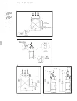
Page 22: ...22 GRIDSHIELD 3P 3SP RECLOSER 21 3SP compact frame front view 22 3SP side mount front view 23 3SP side mount side view 23 22 21 0 8 ...

Page 23: ...lt the frame to the concrete pad Adjust the upper portion of the frame to the desired height The frame allows for adjustments in 3 inch increments 3 Remove the lifting brackets from the frame and attach them to the sides of the recloser If you are using a 3SP unit use the lifting straps around the individual pole body 4 Lift the recloser or the poles if it is a 3SP unit over the top of the frame a...

Page 24: ... 3P 3SP RECLOSER 29 30 27 GridShield 3P substation mount front view 28 GridShield 3P substation mount side view 2 29 GridShield 3SP substation mount front view 30 GridShield 3SP substation mount side view 28 27 0 8 ...

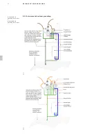
Page 25: ... find a standard NEMA 2 hole drilled unpainted stainless steel pad at the back for grounding refer to figure 31 In 3SP units each pole bucket has a grounding point located underneath refer to figure 32 If voltage transformers are being used they should be grounded to the main ground wire that leads from the recloser to the ground 31 Grounding pad on recloser s HV tank 32 Grounding on bucket of ind...

Page 26: ...26 GRIDSHIELD 3P 3SP RECLOSER 8 2 1 Pole mounted recloser grounding 34 GridShield 3P grounding connections 35 GridShield 3SP grounding connections 34 35 0 8 ...

Page 27: ...27 INSTALL ATION 8 2 2 Substation mount recloser grounding 36 GridShield 3P substation mount grounding 36 0 8 ...

Page 28: ...e inputs directly to the back of the relay If you have optional voltage sensing cables from external sensors they can also provide voltage inputs to the back of the relay If you want to obtain control power from one of the three VTs used for metering you need to add jumpers to the control cabinet distribution terminal block to connect one of the voltage sources to the control power input Follow th...

Page 29: ... relay s software a For RER615 and RER620 navigate to Configuration Analog Inputs Voltage VA VB VC VT Amplitude Correction on the front panel to enter these correction factors b For RER615 and RER620 use PCM600 to update these settings by going to IED Configuration Configuration Analog Inputs Voltage 3U VT Right click on the parameter settings to select and update them 8 7 Final inspection When in...

Page 30: ... pushed deeper into the interrupter by the operating mechanism The over travel spring at the upper end of the operating rod ensures proper contact pressure in the closed position Contact erosion reduces the compression of the over travel spring increasing contact travel the actuator s total travel is fixed To easily confirm allowable contact erosion use the 2 5 mm gauge provided with the recloser ...

Page 31: ...o ohms Measure the resistance across terminals H1 and H2 when the contacts are closed 6 Measure the actuator coil resistance for each phase The coil resistance should not exceed 10 ohms Refer to table 2 for the correct set of pins to measure the coil resistance Table 2 Actuator coil resistance measurement pins 24 pin control 32 pin control 42 pin control Phase A Pins 10 22 Pins Y Z Pins 2 3 Phase ...

Page 32: ... preferred ratio Alternatively it is also possible to change the ratio after the unit is installed in the field To change the CT ratio follow the steps below 1 For single tank units remove the front door For 3SP units remove the pole bucket to access the circuit board mounted on the actuator assembly see figure 38 2 Locate the J1 terminal on the circuit board 3 Obtain a terminal block jumper strip...

Page 33: ... located on the ACM cabinet turns off Avoid touching anything during this time 3 Once the designated time has passed turn the screw that secures the IED handle clockwise until it is fully screwed in allowing the handle to move freely 4 Lift the handle to a 90 degree angle with the relay 5 Pull the relay straight out and place it on a surface that is safe from electrostatic discharge ESD Installati...

Page 34: ...e disposal Raw material Recycle Environmental effects and reuse purposes Iron Yes Separate use instead of new source ore Stainless steel Yes Separate use instead of new source ore Copper Yes Separate use instead of new source ore Brass Yes Separate use instead of new source ore Aluminum Yes Separate use instead of new source ore Zinc Yes Separate use instead of new source ore Thermoplastic Yes Mak...

Page 35: ...gencies No warranties expressed or implied including warranties of fitness for a particular purpose or merchantability or warranties of fitness for a particular purpose or merchantability or warranties arising from course of dealing or usage of trade are made regarding the information recommendations descriptions and safety notations contained herein In no event will ABB be responsible to the user...

Page 36: ...abinet with RER615 RER620 or Beckwith M 7679 ABB 24 pin control cabinet with RER620 ABB 24 pin low profile control cabinet with RER620 Front view Front view Front view Side view Side view Side view NOTE Please refer to SEL 651R instruction manual for SEL control cabinet dimensions 1 2 ...

Page 37: ...closer nameplate 3SP 41 42 Rev Pages Change description Date initial D All Updated content with detailed pictures Mar 2012 E All Added GridShield 3SP related content Added measurement values for maintenance Added dual voltage sensing unit related information Dec 2020 DP F All General update Oct 2023 CV 1 2 ...

Page 38: ...particulars shall prevail ABB Inc does not accept any responsibility whatsoever for potential errors or possible lack of information in this document We reserve all rights in this document and in the subject matter and illustrations contained therein Any reproduction disclosure to third parties or utilization of its contents in whole or in parts is forbidden without prior written consent of ABB In...

Page 39: ...IMPORTANT SAFET Y NOTES AND WARNINGS 39 ...

Page 40: ...1VAL265401 MB REV D OCTOBER 2023 Copyright 2023 ABB All rights reserved ABB Inc 305 Gregson Dr Cary NC 27511 E Mail customer service group us abb com www abb com mediumvoltage ...

Reviews: