22
Installation and maintenance guide
1ZSC000563-AAB EN, REV. 6, 2019-09-12
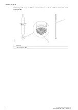
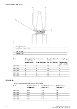
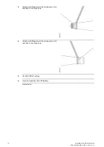
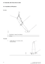
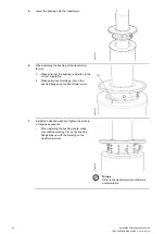
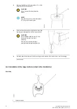
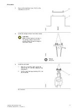
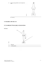
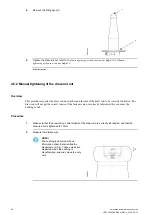
4.3.2 Installation with fixed bottom contact
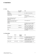
G006208
1
Bottom contact
2
Bushing
3
Pulling ring
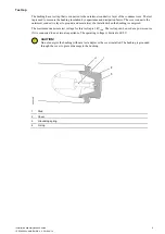
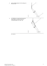
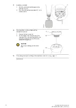
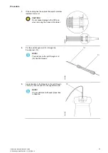
Procedure
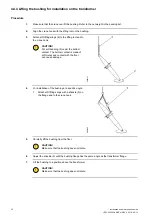
1.
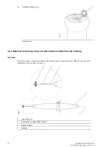
If the bushing has the optional transport container
installed, remove it.
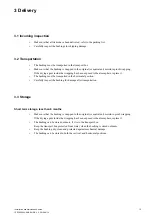
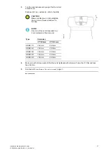
CAUTION!
Do not cause damage to the RIP-core
when removing the transport container.
G005091
Summary of Contents for GSBK 170
Page 46: ...46 Installation and maintenance guide 1ZSC000563 AAB EN REV 6 2019 09 12 ...
Page 52: ...52 Installation and maintenance guide 1ZSC000563 AAB EN REV 6 2019 09 12 ...
Page 54: ...54 Installation and maintenance guide 1ZSC000563 AAB EN REV 6 2019 09 12 ...
Page 62: ...62 Installation and maintenance guide 1ZSC000563 AAB EN REV 6 2019 09 12 ...
Page 66: ...66 Installation and maintenance guide 1ZSC000563 AAB EN REV 6 2019 09 12 ...
Page 70: ......
Page 71: ......


