Installation and maintenance guide
1ZSC000563-AAB EN, REV. 6, 2019-09-12
51
9.
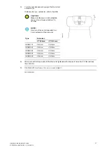
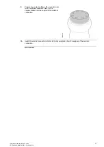
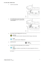
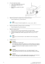
Connect the outer terminal of the bushing to the external connections.
End of instruction
5.2.4 Measurement of through-resistance
Overview
The method to use for measuring the through-resistance depends on the design of the transformer. In general,
a current is applied from bushing to bushing. The voltage drop from the outer terminal to outer terminal is
measured. The resistance is calculated with Ohm's law, R=U÷I.
(R: total circuit resistance, U: measured voltage drop, I: through-current).
The total through-resistance is the sum of the transformer winding, lead resistance, the bushing conductor,
and contact resistance. The additional resistance from the bushing conductor should not be more than
150 μΩ. Because the through-resistance of the HV winding of a typical power transformer is in the order of
0.1 to 1 Ω, this is a very rough method that can only be used to detect very large faults in the current path,
such as open circuits.
Small faults in the current path can only be detected by making sensitive measurements across each
connection point, or by measuring the temperature increase during operation with an infrared sensitive
camera (thermovision).
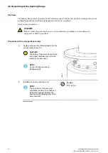
The through-resistance of an installed bushing can only be measured from the outer terminal of one bushing,
to the outer terminal of the other bushing on the same transformer winding. The through-resistance will
include the resistance of both bushings, all connections and the transformer winding.
Procedure
1.
Record the temperature of the transformer winding.
NOTE!
The resistance of metals depends on their temperature. Because the transformer winding
usually dominates the total resistance, the average winding temperature at the time of
measurement must be recorded.
2.
Measure the through-resistance from outer terminal to outer terminal.
3.
Calculate the measured resistance to the reference temperature. Then compare the calculated
resistance to the reference resistance.
A difference of less than 2% is acceptable.
NOTE!
The transformer manufacturer gives the reference temperature for through-resistance
measurements.
4.
If the calculated difference of resistance is more than 2% from the reference resistance:
1.
Make sure that the external connections have low resistance, and make sure that the outer
terminal and the internal connections are correctly installed.
2.
Measure the through-resistance again.
5.
If the calculated difference of resistance again is more than 2%:
•
Wait 24 hours and do steps 1 through 5 again.
End of instruction
Summary of Contents for GSBK 170
Page 46: ...46 Installation and maintenance guide 1ZSC000563 AAB EN REV 6 2019 09 12 ...
Page 52: ...52 Installation and maintenance guide 1ZSC000563 AAB EN REV 6 2019 09 12 ...
Page 54: ...54 Installation and maintenance guide 1ZSC000563 AAB EN REV 6 2019 09 12 ...
Page 62: ...62 Installation and maintenance guide 1ZSC000563 AAB EN REV 6 2019 09 12 ...
Page 66: ...66 Installation and maintenance guide 1ZSC000563 AAB EN REV 6 2019 09 12 ...
Page 70: ......
Page 71: ......

