36
Electro-pneumatic positioner TZIDC
41/18-79 EN
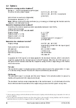
4.2 Options
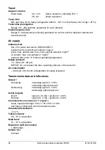
Module for analog position feedback
1
Range 4 ... 20 mA (configurable split ranges)
Two-wire circuitry, power supply
24 V DC (10...30 V DC)
48 V DC (20...48 V DC, no explosion
protection)
Action direct or reverse (configurable)
Characteristic deviation
<
1 %
Note
: Without a signal from the positioner (e.g. no energy or initializing) the module sets the
output to > 20 mA (alarm level)
Module for digital position feedback
1
2 switches for position signals (position adjustable between 0 and 100%,
ranges cannot overlap)
Current circuits to DIN 19234/NAMUR
Supply voltage
5...11 V DC
Signal current < 1.0 mA
logical “0”
Signal current > 2.0 mA
logical “1”
Effective direction:
normally logical “0” or logical “1”
(configurable)
Module for the shutdown function
2
Supply voltage
24 V DC (20...30 V DC)
(electrically isolated from the input signal)
Safe position is activated when
voltage < 5 V
AK approval
AK 4 to DIN V 19250
Test report No.
101/S01/148
Explosion protection
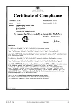
see certificates
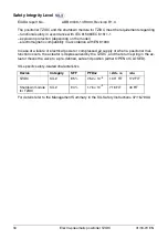
SIL
A separate 24 V DC signal is normally applied to the shutdown module, which connects th-
rough the signal from the microprocessor to the I/P module. When the 24 V DC signal is in-
terrupted, the I/P module executes the respective safety function, depending on the mecha-
nical construction.
Fail safe:
The positioner output 1 is depressurized, and the valve moves to the safe position. In case
of a double-acting actuator the second output is additionally pressurized.
Fail-freeze:
The pneumatic ouput 1 is closed, and the valve “freezes” in its current position. In case of a
double-acting actuator both outputs are closed.
The shutdown module works independently of the mother board, i.e. all information from the
final control element is available in the supervisory process control system at any time.
1. The module for analog position feedback and the module for digital position feedback plug in separate slots and can
be used together.
2. The module for the shutdown function uses the same space as the module for analog feedback and the module for
digital feedback and cannot be plugged in and run together with any of them.
Summary of Contents for HART Industrial IT enabled TZIDC
Page 38: ...38 Electro pneumatic positioner TZIDC 41 18 79 EN 5 Certificates ...
Page 39: ...41 18 79 EN Electro pneumatic positioner TZIDC 39 ...
Page 40: ...40 Electro pneumatic positioner TZIDC 41 18 79 EN ...
Page 41: ...41 18 79 EN Electro pneumatic positioner TZIDC 41 ...
Page 42: ...42 Electro pneumatic positioner TZIDC 41 18 79 EN ...
Page 43: ...41 18 79 EN Electro pneumatic positioner TZIDC 43 ...
Page 44: ...44 Electro pneumatic positioner TZIDC 41 18 79 EN ...
Page 45: ...41 18 79 EN Electro pneumatic positioner TZIDC 45 ...
Page 46: ...46 Electro pneumatic positioner TZIDC 41 18 79 EN ...
Page 47: ...41 18 79 EN Electro pneumatic positioner TZIDC 47 ...
Page 48: ...48 Electro pneumatic positioner TZIDC 41 18 79 EN ...
Page 49: ...41 18 79 EN Electro pneumatic positioner TZIDC 49 ...
Page 51: ...41 18 79 EN Electro pneumatic positioner TZIDC 51 ...
Page 52: ...52 Electro pneumatic positioner TZIDC 41 18 79 EN ...
Page 53: ...41 18 79 EN Electro pneumatic positioner TZIDC 53 ...
Page 61: ...41 18 79 EN Electro pneumatic positioner TZIDC 61 ...
Page 62: ...62 Electro pneumatic positioner TZIDC 41 18 79 EN ...
Page 63: ...41 18 79 EN Electro pneumatic positioner TZIDC 63 ...
Page 64: ...64 Electro pneumatic positioner TZIDC 41 18 79 EN ...

