background image

41/18-79 EN

Electro-pneumatic positioner TZIDC

47

Summary of Contents for HART Industrial IT enabled TZIDC

Page 1: ...Operating Instructions 41 18 79 EN Electro Pneumatic Positioner TZIDC for 4 20 mA two wire technology Software Revision 2 00 ...

Page 2: ...49 551 905 555 CCC support deapr de abb com Note More information e g regarding configuration operation and ordering details is available on CD Copyright 2005 by ABB Automation Products GmbH Modifications reserved This document is subject to copyright It is intended to help the user operate the equipment safely and efficiently The content may not be copied or reprodcued either in part or in full w...

Page 3: ...t use 9 1 5 Qualified personnel 10 2 Manufacturer s information 10 2 1 Delivery 10 2 2 CE compliance information 10 3 Installing and commissioning 11 3 1 Mechanical mounting 11 3 1 1 General 11 3 1 2 Operating conditions at the installation site 12 3 1 3 Mounting the positioner to linear actuators 12 3 1 4 Mounting the positioner to rotary actuators 17 3 2 Pneumatic connection 20 3 2 1 Safety inst...

Page 4: ... cable in the housing 24 3 3 5 Make the electrical connection 25 3 4 Commissioning 26 3 4 1 Commissioning procedure 26 3 4 2 Operating modes overview and selection 27 3 4 3 Parameter setting example 28 3 5 Functional test maintenance 29 3 5 1 Functional test of the shutdown module 30 4 Technical data 31 4 1 Basic model 31 4 2 Options 36 5 Certificates 38 Appendix A Parameter overview 65 ...

Page 5: ...mbol Signal Word Definitions DANGER DANGER indicates an imminently hazardous situation which if not avoided will result in death or serious injury High level of risk WARNING WARNING indicates a potentially hazardous situation which if not avoided could result in death or serious injury Medium level of risk CAUTION CAUTION indicates a potentially hazardous situation which if not avoided could resul...

Page 6: ...ved The TZIDC positioner has been designed and tested in accordance with DIN VDE 0411 Part 1 EN 61 010 Part 1 Safety Requirements for Electronic Measuring Apparatus based on IEC Publication 348 and has been delivered in a safe condition In order to retain the device in a safe condition and ensure safe operation attentively read and follow the instructions given in the sections marked with the resp...

Page 7: ...ery two years at the latest Follow the instructions in chapter 3 5 1 NOTICE Protection class IP 65 NEMA 4 X is achieved only when the splash guard cap is in place Do not use the positioner without the cap WARNING Observe the accident prevention rules of the Employers Liability Insur ance Association Observe the safety instructions for the pneumatic actuator used The actuator s high actuating power...

Page 8: ...ection VDE 0165 or EN 60079 and the special requirements and specifications for your devices see the following chapter Explosion protection and chapter Certificates starting on page 38 NOTICE Power supply Exclusively connect signal circuits with load independent 4 20 mA current to terminals 11 12 Direct connection of a power supply e g a 24 V DC power supply unit will damage the input The maximum ...

Page 9: ...he data sheet 18 0 22 EN Any other use is considered as incorrect The signal current circuit and the input and output circuitry must meet the explosion pro tection requirements stipulated in the certificates see chapter Certificates starting on page 38 The maximum permissible ambient temperature range of 40 C to 85 C when using proximity switches of type SJ2 S1N NO 25 C to 85 C must not be exceede...

Page 10: ...or are added to the delivery as individual items Check items and scope of the delivery by means of the catalog numbers to see if types and quantities are in accordance with your order If the positioner is delivered already mounted to the actuator the positioner accessories and actuator or final control element are considered as a common delivery item A list of catalog numbers and details of the di...

Page 11: ...r ensure that the transfer of the stroke or rota tion angle for the position feedback is correct The maxi mum rotation angle is 60 for mounting to linear actuators and 120 for mount ing to rotary actua tors The minimum angle is always 25 Fig 2 Operating range 1 2 Fig 3 Positioner ranges TZID C 60 60 30 30 100 0 100 0 Sensor range for rotary actuators Operating range for linear actuators Operating ...

Page 12: ...ioner to a linear actuator according to DIN IEC 534 lateral mounting to NAMUR comprising the following parts Tools required Wrench 10 mm 13 mm Allen key 4 mm WARNING Before installing check to ensure that the specifications in terms of safety and control applicable to the TZIDC positioner will not be exceeded at the installation site of the actuator or final control element Lever 1 0 with follower...

Page 13: ...crews Slip the spring 2 onto the bolt with the follower pin 1 Slip the plastic washer 3 onto the bolt and compress the spring with it Insert the bolt with com pressed spring into the oblong hole in the lever 4 and fasten it in the desired position using the plain washer 5 and nut 6 at the lever the scale on the lever indicates the link point for the stroke range Slip the plain washer 8 onto the sc...

Page 14: ...sembled positioner with the angle bracket 5 still loose in such a way against the actuator that the follower pin on the lever introduces into the follower guide in order to determine the bore holes of the positioner to be used for the angle bracket Fasten the angle bracket 5 with screws 6 and plain washers 7 to the correspond ing bore holes in the positioner case if possible tighten the screws eve...

Page 15: ...e inner side of the columnar yoke through the holes in the angle bracket Slip on the plain washers 4 and nuts 5 Hand tighten the nuts evenly IMPORTANT Adjust the height of the positioner at the cast iron yoke or the columnar yoke until the lever is horizontal at visual check at half valve stroke Check the unit for proper mounting after having made the pneumatic and electrical connection see chapte...

Page 16: ...on sensor s rotation angle is increased shifting to the outside decreases the angle Set the stroke range in such a way that the used rotation angle of the position sensor is as great and as symmetrical around the center position as possible Recommended range for linear actuators between 28 and 28 Minimum angle 25 IMPORTANT After mounting check whether the positioner operates within the sensor rang...

Page 17: ...ools required Wrench 10 mm 13 mm Allen key 3 mm Adapter 1 0 with spring 1 4 Four screws M6 1 1 four spring washers 1 2 and four plain washers 1 3 for fastening the bracket 2 0 to the positioner Mounting bracket 2 0 Four screws M5 2 1 four spring washers 2 2 and four plain washers 2 3 for fastening the bracket to the actuator 1 3 1 0 1 1 2 0 2 1 2 2 2 3 1 2 1 4 Fig 11 Mounting kit for rotary actuat...

Page 18: ...osition and the direction of rotation it must be determined in which position the feedback shaft 1 of the positioner must be pre adjusted and in which position the adapter 2 must be placed to enable the positioner to travel within the correct range the arrow on the rear of the device must travel within the admissible range for details see Fig 2 on page 11 Pre adjust the feedback shaft Place the ad...

Page 19: ... After mounting check whether the actuator s operating range is in accor dance with the positioner s sensor range Check the unit for proper mounting after having made the pneumatic and electrical connection see chapter Commissioning on page 26 M5 screws Fig 14 Attaching the positioner to the actuator ...

Page 20: ...dent prevention rules of the Employers Liability Insur ance Association Observe the safety instructions for the pneumatic actuator used The actuator s high actuating power may cause injuries NOTICE Take suitable precautions to ensure that even in case of malfunctions the positioner s max admissible operating pressure of 6 bar 90 psi is not exceeded Otherwise the positioner and or the actuator may ...

Page 21: ... in the bottom plate of the case as seen in the illustration below Do not use a screw driver for this purpose Mark Connection piping Air supply pressure 1 4 6 bar 20 90 psi OUT1 Output pressure to actuator OUT2 Output pressure to actuator second output for double acting actuators NOTICE Protection class IP 65 NEMA 4 X is achieved only when the splash guard cap is in place Do not use the positioner...

Page 22: ...devices see chapter Certificates starting on page 38 NOTICE Observe the following instructions They are essential to proper operation and functionality of the positioner General Do not expose the terminals to strain Technical data When connecting the device make sure that the electrical specifica tions in chapter 4 Technical data are observed Power supply Exclusively connect signal circuits with l...

Page 23: ...lows 1 Module for analog position feedback 2 Module for digital position feedback or service switch of the shutdown module 3 Module for digital position feedback or terminals of the shutdown module 4 Kit for digital position feedback either proximity switches or 24 V microswitches 5 Same as 4 6 Digital output DO 7 Digital input DI 8 4 20 mA signal 9 Grounding screw Fig 17 Cable entry Pipe plug Cab...

Page 24: ... the green yellow protective ground conductor 1 and the two 4 20 mA signal lines 2 to the specified length and remove approx 6 mm of the insulation 2 Put the protective hose 4 on the ferrite tube 3 3 Insert all wires through the cable gland 6 and the ferrite tube 3 Make sure that the end of the cable sheath 5 protrudes into the connection compartment Fasten the cable gland 4 Fasten the protective ...

Page 25: ...onding screw terminals and hand tighten the screws access from the side 83 84 DI AI DO AO SW 1 SW 2 10V 30V DC 4 20mA 81 82 11 12 24V DC 12V 30V 4 20 mA L 1mA H 2mA 5 11V DC L 1mA H 2mA 5 11V DC L 1mA H 2mA 5 11V DC 31 32 41 42 51 52 41 42 Limit 2 max 24V max 2A 41 42 43 51 52 53 Limit 2 Limit 1 NC NO NC NO Limit 1 51 52 85 86 24V DC 20V 30V L 1mA H 2mA 5 11V DC L 1mA H 2mA 5 11V DC Digital input ...

Page 26: ...n and hold it down until the countdown is finished Then release MODE Standard autoadjustment is started or For rotary actuators 1 Press and hold ENTER until ADJ_ROT is displayed then release Press ENTER again and hold it down until the countdown is finished Then release ENTER Standard autoadjustment is started When the autoadjustment function is finished successfully the parameter settings are aut...

Page 27: ...g operation that may lead to mismatches in the long run Therefore it is recom mended to use this operating mode for some hours only and then switch the posi tioner to mode 1 1 Control without adaptation Positioning not active For quick motion Press and together Mode Mode display Position display 1 0 Control with adaptation of control parameters 1 1 Control without adaptation of control parameters ...

Page 28: ...n has run down from 3 to 0 Release and is displayed 2 Change over to parameter group 3 _ Simultaneously press and hold MODE and ENTER Additionally 2 x briefly press is displayed Release MODE and ENTER is displayed 3 Select parameter 3 2 Zero position Press and hold MODE Additionally 2 x briefly press is displayed Release MODE 4 Change parameter setting Briefly press to select CTCLOCKW IMPORTANT An...

Page 29: ...ror free and maintenance free operation always supply the positioner with instrument air exempt from oil water and dust according to DIN ISO 8573 1 purity and oil content acc to Class 3 pressure dew point 10 K below the operating temperature We recommend to check the integrated air filter on a regular basis and replace it if required If the optionally installed filter regulator is installed it has...

Page 30: ... the actuator is depres surized properly 3 Set the slide switch to the On position in the middle again 4 Replace the cover WARNING If the optional shutdown module is used it must be subject to a functional test every two years at the latest to ensure full operational reliability in compliance with DIN V 19250 Otherwise the AK4 approval will lapse 41 42 Limit 2 Limit 1 51 52 11 12 83 84 81 82 1 85 ...

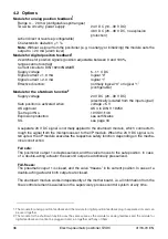
Page 31: ... safe device Digital input Control voltage 24 V DC 12 30 V DC 0 10 V DC Logical 0 12 30 V DC Logical 1 Current max 4 mA Digital output control circuit to DIN 19234 NAMUR Supply voltage 5 11 V DC Current 1 0 mA logical 0 Current 2 0 mA logical 1 Effective direction Normally logical 0 or logical 1 configurable Output Range 0 6 bar 0 90 psi Air capacity at supply pressure of 1 4 bar 20 psi 5 0 kg h 3...

Page 32: ...y 5 mg m3 oil content max concentration 1 mg m3 pressure dew point 10 K below operating temperature Supply pressure 1 4 6 bar 20 90 psi NOTICE Do not exceed the max operating pressure of the actuator Air consumption 0 03 kg h 0 015 scfm independent of supply pressure Transmission data and influences Output 1 Increasing increasing signal 0 100 increasing output pressure 1 Decreasing increasing sign...

Page 33: ...40 C to 85 C for operation storage and transport 25 C to 85 C with proximity switches SJ2 S1N NO Relative humidity Operational with closed case and air supply switched on 95 annual average condensation permissible Transport and storage 75 annual average non condensing Case Material Protections Aluminum protection class IP 65 NEMA 4X Surface color Electrostatic dipping varnish with epoxy resin stov...

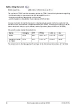
Page 34: ...rdance with EN 61000 In case of a failure of electrical power or compressed air supply or when a positioner mal function occurs the actuator is depressurized by the TZIDC and the return spring in the ac tuator moves the valve to a pre defined safe end position either OPEN or CLOSED SIL specific safety related characteristics For details refer to the Management Summary in the SIL Safety Instruction...

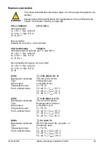
Page 35: ... II 2G EEx ib IIC Temperature class T4 T5 T6 Perm ambient temp T4 40 C Tamb 85 C T5 40 C Tamb 50 C T6 40 C Tamb 35 C ATEX II 3G EEx n A II T6 Examination certificate TÜV 02 ATEX 1943 X Type Explosion proof Zone 2 Device class II 3G EEx n A II Temperature class T4 T5 T6 Perm ambient temp T4 40 C Tamb 85 C T5 40 C Tamb 65 C T6 40 C Tamb 50 C IECEx Ex ib IIC T6 Examination certificate IECEx TUN 04 00...

Page 36: ...losion protection see certificates SIL see page 34 A separate 24 V DC signal is normally applied to the shutdown module which connects th rough the signal from the microprocessor to the I P module When the 24 V DC signal is in terrupted the I P module executes the respective safety function depending on the mecha nical construction Fail safe The positioner output 1 is depressurized and the valve m...

Page 37: ...cal state Digital position feedback with 24 V microswitches Two microswitches for independent position signaling Switching points adjustable between 0 and 100 Voltage max 24 V AC DC Current load max 2 A Contact surface 10 µm gold AU Mechanical position indicator Indicator disk in enclosure cover linked with positioner feedback shaft Proximity switch Position Lim 1 Lim 1 Lim 2 Lim 2 SJ2 SN NC 0 1 1...

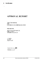
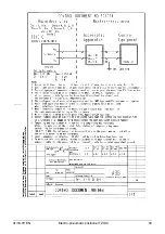
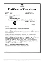
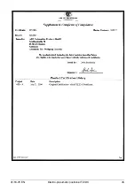
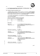
Page 38: ...38 Electro pneumatic positioner TZIDC 41 18 79 EN 5 Certificates ...

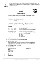
Page 39: ...41 18 79 EN Electro pneumatic positioner TZIDC 39 ...

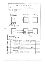
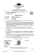
Page 40: ...40 Electro pneumatic positioner TZIDC 41 18 79 EN ...

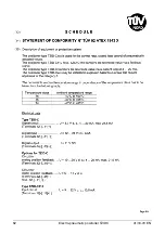
Page 41: ...41 18 79 EN Electro pneumatic positioner TZIDC 41 ...

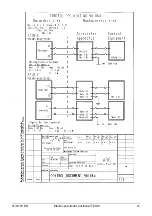
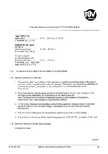
Page 42: ...42 Electro pneumatic positioner TZIDC 41 18 79 EN ...

Page 43: ...41 18 79 EN Electro pneumatic positioner TZIDC 43 ...

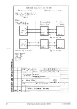
Page 44: ...44 Electro pneumatic positioner TZIDC 41 18 79 EN ...

Page 45: ...41 18 79 EN Electro pneumatic positioner TZIDC 45 ...

Page 46: ...46 Electro pneumatic positioner TZIDC 41 18 79 EN ...

Page 47: ...41 18 79 EN Electro pneumatic positioner TZIDC 47 ...

Page 48: ...48 Electro pneumatic positioner TZIDC 41 18 79 EN ...

Page 49: ...41 18 79 EN Electro pneumatic positioner TZIDC 49 ...

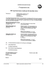
Page 50: ... positioner TZIDC 41 18 79 EN Important Only the 7th Supplement to the certificate TÜV 98 ATEX 1370 X is shown here since the Supplements 2 to 6 do not contain information that is relevant for these operating instructions ...

Page 51: ...41 18 79 EN Electro pneumatic positioner TZIDC 51 ...

Page 52: ...52 Electro pneumatic positioner TZIDC 41 18 79 EN ...

Page 53: ...41 18 79 EN Electro pneumatic positioner TZIDC 53 ...

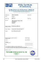
Page 54: ...al Apparatus Positioner type TZIDC xxx Optional accessory Type of Protection Intrinsic safety Type of protection n Marking Ex ia IIC T6 resp Ex nA II T6 Approved for issue on behalf of the IECEx Certification Body Herbert Stürwold Position Head of IECExCB Signature for printed version Date 1 This certificate and schedule may only be reproduced in full 2 This certificate is not transferable and rem...

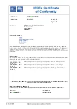
Page 55: ...out in IECEx Scheme Rules IECEx 02 and Operational Documents as amended STANDARDS The electrical apparatus and any acceptable variations to it specified in the schedule of this certificate and the identified documents was found to comply with the following standards IEC 60079 0 2000 Edition 3 1 Electrical apparatus for explosive gas atmospheres Part 0 General requirements IEC 60079 11 1999 Edition...

Page 56: ...emperature range T4 40 C to 85 C 40 C to 85 C 40 C to 85 C T5 40 C to 50 C 40 C to 55 C 40 C to 65 C T6 40 C to 35 C 40 C to 40 C 40 C to 50 C CONDITIONS OF CERTIFICATION YES as shown below Special condition for safe use of intrinsically safe Positioners The operation of the local communication interface LKS and of the programming interface X5 is only allowed outside of the hazardous explosive are...

Page 57: ...41 18 79 EN Electro pneumatic positioner TZIDC 57 IECEx Certificate of Conformity Certificate No IECEx TUN 04 0015X Date of Issue 2004 07 29 Issue No 0 Page 4 of 4 Additional information pp y ...

Page 58: ...side of the explosive hazardous area Optionally the following modules are allowed to be used Mechanical digital feedback terminals Limit1 51 52 resp Limit2 41 42 in type of protection Intrinsic Safety Ex ib IIC Maximum values see IEC Certificate No proximity switches of the company Pepperl Fuchs GmbH Digital feedback terminals 51 52 resp 41 42 in type of protection Intrinsic Safety Ex ib IIC only ...

Page 59: ...idal linear Local interface for communication LKS and programming interface X5 For the connection to a programmer resp a PC outside of the explosive hazardous area Optionally the following modules are allowed to be used Shutdown switch input terminals 51 52 resp 85 86 in type of protection Intrinsic Safety Ex ia IIC resp Ex ib IIC only for the connection to a certified intrinsically safe circuit w...

Page 60: ...put terminals 83 84 U 11 VDC Optionally the following modules are allowed to be used with type TZIDC Digital feedback terminals 51 52 resp 41 42 U 5 11 VDC Analogue feedback terminals 31 32 U 10 30 VDC 4 20 mA max 21 5 mA Type TZIDC 110 Input circuit terminals 11 12 U 9 32 VDC 10 5 mA Type TZIDC 120 Input circuit terminals 11 12 U 9 32 VDC 11 5 mA Additionally the following modules are allowed to ...

Page 61: ...41 18 79 EN Electro pneumatic positioner TZIDC 61 ...

Page 62: ...62 Electro pneumatic positioner TZIDC 41 18 79 EN ...

Page 63: ...41 18 79 EN Electro pneumatic positioner TZIDC 63 ...

Page 64: ...64 Electro pneumatic positioner TZIDC 41 18 79 EN ...

Page 65: ... output DIRECT REVERSE DIRECT P2 4 SHUT_CLS Shut off range 0 OFF 0 1 45 0 1 0 P2 5 RAMP Setpoint ramp up OFF 1 200 sec OFF P2 6 RAMP Setpoint ramp down OFF 1 200 sec OFF P2 7 SHUT_OPN Shut off range 100 OFF 55 0 100 OFF P2 8 EXIT Return to operating level Command function is executed P3 _ ACTUATOR P3 0 MIN_RGE Min of operating range 0 0 100 0 0 0 P3 1 MAX_RGE Max of operating range 0 0 100 0 100 0...

Page 66: ...UATOR Actuator type LINEAR ROTARY LINEAR P6 3 SPRNG_Y2 Spring action Y2 CLOCKWISE CTCLOCKWISE CTCLOCKWISE P6 4 ADJ_MODE Autoadjustment mode FULL STROKE CTRL_PAR ZERO_POS LOCKED FULL P6 5 EXIT Return to operating level Command function is executed P7_ CTRL_PAR P7 0 KP KP value up 1 0 400 0 5 0 P7 1 KP KP value down 1 0 400 0 5 0 P7 2 TV TV value up 10 800 msec 200 P7 3 TV TV value down 10 800 msec ...

Page 67: ..._LO ACTIV_HI P9 2 SW2_LOG SW2 logic level ACTIV_HI ACTIV_LO ACTIV_HI P9 3 TEST Test ALARM_ON SW1_ON SW2_ON ALL_ON NONE NONE P9 4 EXIT Return to operating level Command function is executed P10 _ DIG_IN P10 0 FUNCTION Function selection NONE POS_O POS_100 POS_HOLD CNF_LOCK OP_LOCK ALL_LOCK NONE P10 1 EXIT Return to operating level Command function is executed P11 _ FS IP P11 0 FAIL_POS Safe positio...

Page 68: ...TPOINT P3 ACTUATOR P4 MES P5 ALARMS P6 MAN_ADJ P7 CTRL_PAR P8 ANLG_OUT P9 DIG_OUT PI0 DIG_IN PII FS IP I I CTRL_FIX PI 0 PI I PI 2 PI 3 PI 4 PI 5 P2 0 P2 I P2 2 P2 3 P2 4 P2 5 P2 6 P2 7 P2 8 P3 0 P3 I P3 2 P3 3 MODE P4 0 P4 I P4 2 P4 3 P4 4 P4 5 P5 0 P5 I P5 2 P5 3 P5 4 P5 5 P5 6 P5 7 P6 0 P6 I P6 2 P6 3 P6 4 P6 5 P7 0 P7 I P7 2 P7 3 P7 4 P7 5 P7 6 P7 7 P7 8 P7 9 P7 I I P8 0 P8 I P8 2 P8 3 P8 4 P8...

Page 69: ...fy the information contained herein without notice Printed in the Fed Rep of Germany 04 05 ABB 2005 41 18 79 EN Rev C ABB Ltd Salterbeck Trading Estate Workington Cumbria CA14 5DS UK Tel 44 0 1946 830 611 Fax 44 0 1946 832 661 ABB Inc 125 E County Line Road Warminster PA 18974 USA Tel 1 215 674 6000 Fax 1 215 674 7183 ABB Automation Products GmbH Schillerstr 72 32425 Minden Germany Tel 49 551 905 ...

Reviews: