41-971.3M
Type HCB-1 Pilot Wire Relay System
10
Sub 1
619591
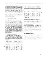
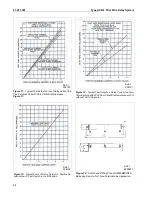
Figure 7:
Typical Operating Characteristics of the HCB-1 Relay System — Maximum Restraint Tap, with 4/1
Insulating Transformers and 2000-Ohm Pilot-wire. VF of Near and Far Relays in Phase or 180° Out-of-Phase.
R
NC
(I), R
NC
(II)
– current transformer ratio at Sta-
tion I and II respectively.
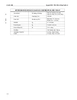
5.2.1. Phase Fault Sensitivity (R1 and Taps)
The phase fault pickup is determined by the B, C and
T taps. In order to operate on the minimum 3-phase
fault current, the T tap should be set for not more
than:
Equ. (8)
In order to prevent operation on load current if the
pilot-wires become open circuited, the T tap should
be set for not less than:
Equ. (9)
The available taps are:
T: 4, 5, 6, 7, 8, 10, 12
Where sufficient fault current is available, it is recom-
mended that the relays be set as follows:
T
I
L
tap
C
(
)
T
;
0.5
I
3
P
tap
B
(
)
=
=
T
I
L
tap
C
(
)
T
;
I
L
2
----
tap
B
(
)
=
=
Summary of Contents for HCB-1
Page 19: ...Type HCB 1 Pilot Wire Relay System 41 971 3M 19 THIS SPACE RESERVED FOR NOTES ...
Page 21: ...Type HCB 1 Pilot Wire Relay System 41 971 3M 21 ...
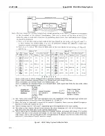
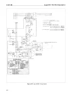
Page 22: ...41 971 3M Type HCB 1 Pilot Wire Relay System 22 Figure 10 Typical HCB 1 Relay System ...
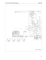
Page 23: ...Type HCB 1 Pilot Wire Relay System 41 971 3M 23 Sub 15 4810D98 ...
Page 27: ...Type HCB 1 Pilot Wire Relay System 41 971 3M 27 THIS PAGE RESERVED FOR NOTES ...


