41-971.3M
Type HCB-1 Pilot Wire Relay System
14
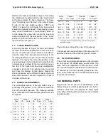
the upper tap plate and Terminal 2. Energize the
relay with 1
79
= 2.05 amperes (terminals 7 and 9).
The measured open-circuit voltage, V
F
, should be:
V
F
= .8
±
5% volts with tap settings C and H. Repeat
this voltage measurement with I
59
= 3.44 amperes.
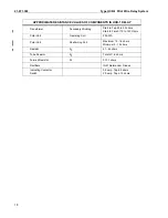
7.2.3. Operating Unit
The following test will check the polar unit calibration
and the performance of the rectifiers. Connect a vari-
able non-inductive resistor across the high-voltage
terminals of the insulating transformer (H1 to H4),
and connect dc millimeters in series with the operat-
ing and restraining coils of the polar unit by opening
these circuits. (The restraint can be opened at the
tap circuit for max. and min. restraint. The operating
circuit has to be opened at the polar unit. The operat-
ing coil terminals are the rear terminals of the polar
unit.) These millimeters should have low resistance
and should be capable of reading in the order of 20
to 25 mA in the operating coil and 100 to 150 mA in
the restraining circuit. Using C, H, and 4, energize
the relay with I35 = 10 amperes (terminals 3 and 5)
and increase the variable resistance across the insu-
lating transformer high-voltage terminals until the
relay just trips. The values obtained should conform
to the following equations:
For minimum restraint:
I
O
= 0.12I
R
+ 7
For maximum restraint:
I
O
= 0.16I
R
+ 7
where I
O
and I
R
are operating and restraining coil
currents, respectively, in milliamperes. The results
are subject to variations between individual relays,
due to different exciting impedances of the insulating
transformers. However, the value should never be
lower than:
For minimum restraint:
I
O
= 0.12I
R
+ 74
For maximum restraint:
I
O
= 0.16I
R
+ 4
7.3.
CALIBRATION PROCEDURE
If the factory calibration has been disturbed, the fol-
lowing procedure should be followed to recalibrate
the relay.
7.3.1. Filter Calibration
This adjustment is performed by means of the taps
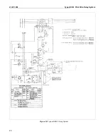
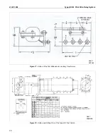
on the formed wire resistor (see Figure 2 for loca-
tion).
1.
Remove tap screw from upper tap plate and set
lower tap screws in A and H.
2.
Connect voltmeter (low-reading, high resistance
rectox) across tap A and the common of the
upper tap block.
3.
Pass 10 amperes ac into terminal 7 and out ter-
minal 5 of the relay and record voltage (voltage
should be .70 to .80).
4.
Remove voltmeter leads and connect them to
non-adjustable point of formed resistor in rear of
relay and the front of left-hand tube resistor.
(F.V.)
5.
Adjust upper adjustable point of formed resistor
until voltmeter reads 1.73 times voltage of step 3.
6.
Check calibration
a) Set taps on C and H. (T tap removed) pass
10 amps. into terminal 7 and out terminal 9.
Measure the voltage across terminal 5 and
common of upper tap block. (Should be
between 3.8 and 4.0 volts.)
b) Pass 10 amperes into terminal 5 and out ter-
minal 7. Measure voltage across non-adjust-
able point of formed resistor in rear of relay
and the front screw of left-hand tube resistor
(F.V.). Voltage should be equal to 1/3 of volt-
age of step 6a.
7.
Connect voltmeter to middle adjustable point and
upper adjustable point of formed resistor.
8.
Pass 10 amperes into terminal 5 and out terminal
7.
9.
Adjust middle adjustable point until voltage
equals 1/3 of that of step 4.
7.3.2. R
0
Taps
No adjustments can be made on the R
0
resistors.
Value of resistance can be checked by passing 5
amperes ac through terminal 3 and out terminal 5. T
tap must be disconnected. Following voltages should
be measured across terminal 2 and the specified tap
of R
0
.
R
0
Tap Setting
Volts ac
G
H
3.8 to 4.2
7.6 to 8.4
Summary of Contents for HCB-1
Page 19: ...Type HCB 1 Pilot Wire Relay System 41 971 3M 19 THIS SPACE RESERVED FOR NOTES ...
Page 21: ...Type HCB 1 Pilot Wire Relay System 41 971 3M 21 ...
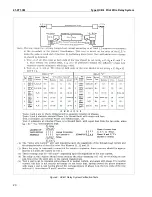
Page 22: ...41 971 3M Type HCB 1 Pilot Wire Relay System 22 Figure 10 Typical HCB 1 Relay System ...
Page 23: ...Type HCB 1 Pilot Wire Relay System 41 971 3M 23 Sub 15 4810D98 ...
Page 27: ...Type HCB 1 Pilot Wire Relay System 41 971 3M 27 THIS PAGE RESERVED FOR NOTES ...


