background image

Type HCB-1 Pilot Wire Relay System

41-971.3M

15

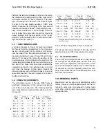
7.3.3. Polar Unit Contact Adjustment

Place a .088 to .095 inch feeler gage between the
right-hand pole face on the armature. This gap
should be measured near the front of the right-hand
pole face. Bring up the backstop screw until it just
makes with the moving contact. Place .045 to .050
gage between moving contact and the stationary
contact on the left-hand side of the polar unit. Bring
up the stationary contact until it just makes with the
gage and lock in place. For relays with double con-
tacts make sure that both upper and lower contacts
make at the same time.

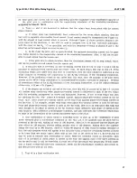
7.3.4. Polar Unit Calibration

Connect the restraint tap link in the position in which
it will be used. Connect terminals X1 and X2 of the
insulating transformer across the pilot-wire terminals
of the relay. Connect the relay taps on 4, C, and H.

The sensitivity of the polar unit is adjusted by means
of two magnetic, screw-type shunts at the rear of the
unit. Looking at the relay front view, turning out the
right-hand shunt decreases the amount of current
required to close to the right-hand stop. Conversely,
drawing out the left-hand shunt decreases the
amount required to trip the relay. In general, the
father out the shunt screws are turned, the greater
the toggles action will be and as a result, the dropout
current will be lower. In adjusting the polar units, be
sure that a definite toggle action is obtained, rather
than a gradual movement of the armature.

Start with both shunts out 4 to 5 turns. Short out the
pilot-wire on the high side of the insulating trans-
former. Momentarily apply 40 amperes from termi-
nals 5 to 3. Now remove the short from H1 to H4 and
apply current to terminals 7 and 9. Adjust the shunts
at the rear of the polar unit such that the unit oper-
ates at 2.10 to 2.15 amperes and resets at 1.0
amperes or higher.

NOTE: Right-hand shunt controls pickup while

left-hand shunt controls dropout.

After this adjustment is complete, short out pilot-wire
and apply 40 amperes momentarily from terminals 5
to 3. Now remove the short from H1 to H4 and check
pickup for I

79

. If value has changed from before, it will

be necessary to re-adjust the right-hand shunt. Sev-

eral trials may be necessary before the relay will
pickup at 2.10 amperes and dropout at 1.0 amperes
or higher. In each case, 40 amperes should be
applied to terminal 5 and 3 with the H1 and H4 termi-
nals shorted before any additional adjustments are
performed on the shunt.

After the shunts have been adjusted, apply 40
amperes momentarily to terminals 3 and 5 of the
relay with the pilot-wire open. Pickup will be approxi-
mately 1.4 amperes with current applied to terminals
7 and 9. This change in pickup is due to a change in
the residual magnetism in the polar unit of the relay.
In the de-energized state, the permanent magnet of
this unit produces a flux or magnetic bias to keep the
contacts open. When the unit is energized, a second
flux (electrical) is produced which either adds to or
subtracts from the magnetic flux. When the electrical
flux is removed, the magnetic structure of the polar
unit is changed. Hence, the flux produced by an
excess of restraint current, adds to the magnetic
bias, and the flux produced by an excess of operat-
ing current subtracts from the magnetic bias. This
characteristic is inherent in the polar unit and has no
effect on the overall performance of the relay.

After the shunt adjustment has been made, change
the input current connections to terminals 3 and 5.
Apply 40 amperes momentarily with H1 and H4 ter-
minals shorted. Remove short and measure pickup
with current applied to terminals 3 and 5. The relay
should trip with I

35

 = 0.45 to 0.55 amperes.

8.0 ROUTINE MAINTENANCE

8.1.

CONTACTS

All contacts should be cleaned periodically. A contact
burnisher, style number 182A836H01, is recom-
mended for this purpose. The use of abrasive mate-
rial for cleaning is not recommended, because of the
danger of embedding small particles in the face of
the soft silver and thus impairing the contact.

8.2.

ICS UNIT

Close the main relay contacts and pass sufficient
direct current through the trip circuit to close the con-
tacts of the ICS. This value of current should not be
greater than the particular ICS tap setting being
used. The indicator target should drop freely.

Summary of Contents for HCB-1

Page 1: ... and a wye connected pilot wire circuit with branches of equal series resistance are required The HCB 1 and HCB relays are not compatible since the filter response is not the same 2 0 CONSTRUCTION The relay consists of a combination positive nega tive and zero phase sequence filter a saturating aux iliary transformer two full wave rectifier units a polar unit a Zener clipper and an indicating cont...

Page 2: ...41 971 3M Type HCB 1 Pilot Wire Relay System 2 Figure 1 Type HCB 1 Relay Without Case Front View ...

Page 3: ...Type HCB 1 Pilot Wire Relay System 41 971 3M 3 Figure 2 Type HCB 1 Relay Without Case Rear View ...

Page 4: ...put VF of a magnitude which is a function of the positive negative and zero sequence components of fault current This voltage VF is impressed on the primary wiring of the saturating transformer The saturating transformer output volt age VS is impressed on the primary wiring of the saturating transformer The saturating transformer output voltage VS is impressed on the primary wir ing of the saturat...

Page 5: ... plus the magnetic restraint or bias expressed in ampere turns 4 0 CHARACTERISTICS The voltage VF impressed by the filter upon the sat urating transformer varies with the tap setting A B C of the relay The sequence network in the relay is arranged for several possible combinations of sequence compo nents For tap C the output of the network will contain the positive negative and zero sequence compo...

Page 6: ... is Equ 2 4 1 SINGLE RELAY PICKUP Pilot wire Open IS Single relay pickup IS is defined as the phase cur rent required to operate one relay with the pilot wire side of the insulating transformer open circuited H1 H4 The single relay pickup point in terms of filter voltage is Equ 3 where T is the saturating transformer tap value Sin gle relay pickup is defined by equating 2 and 3 Equ 4 Current IS va...

Page 7: ...pilot wire shunt capacitance the relays will operate at their nominal pickup point The minimum trip points will vary somewhat from nominal value depending on the pilot wire constants and the magnitude and phase angle of the various relay input currents For example Figure 6 shows the relay operating points for a two terminal line assuming input current one relay only An example of the characteristi...

Page 8: ...mpressed across either insulating trans former H1 H4 Terminals as a result of induction or a Table 4 Insulating Transformer Rate No of Relays 4 1 6 1 RL CS RL CS 2 2000 1 5 4500 0 33 3 500 LEG 1 8 1000 LEG 0 75 rise in station ground potential should be less than 7 5 volts to prevent undesired relay operation For three terminal applications the loop resistance of all legs of the pilot wire must be...

Page 9: ... the seal in contacts of the indicat ing contactor switch will safely carry this current long enough to trip a circuit breaker The indicating contactor switch has two taps that pro vide a pick up setting of 0 2 or 2 amperes To change taps requires connecting the lead located in front of the tap block to the desired setting by means of a screw connection 5 0 SETTINGS There are four settings in the ...

Page 10: ...vely 5 2 1 Phase Fault Sensitivity R1 and Taps The phase fault pickup is determined by the B C and T taps In order to operate on the minimum 3 phase fault current the T tap should be set for not more than Equ 8 In order to prevent operation on load current if the pilot wires become open circuited the T tap should be set for not less than Equ 9 The available taps are T 4 5 6 7 8 10 12 Where suffici...

Page 11: ...tap and maximum restraint In most applications it is not necessary to recalibrate the relay when changing to the minimum restraint tap 5 2 4 Tapped Loads Where one transformer bank is tapped to a line pro tected with two HCB 1 relays the critical point is to set above the fault current flow for a fault on the other side of the bank Set the T for not less than Equ 11 where IPL total secondary fault...

Page 12: ... the relay is performed The HCB 1 is factory calibrated at the following taps R1 C Tap R0 H Tap T 4 Amps If other tap settings are used the HCB 1 relay must be recalibrated at the applied settings to obtain pickup current within 5 of the I L specifications 7 1 MAIN UNIT Connect the relay to the insulating transformer as shown in Figure 8 and set C H 4 and maximum restraint tap With the insulating ...

Page 13: ... Over all calibration can be checked by the procedure described under Acceptance Tests If the relay has been recalibrated in the minimum restraint tap fac tory calibration is made in the maximum restraint tap the RPW test should be made in accordance with Table 6 instead of Table 5 7 2 2 Sequence Filter Remove tap screw from upper tap plate and connect a high resistance voltmeter across the common...

Page 14: ...or maximum restraint IO 0 16IR 4 7 3 CALIBRATION PROCEDURE If the factory calibration has been disturbed the fol lowing procedure should be followed to recalibrate the relay 7 3 1 Filter Calibration This adjustment is performed by means of the taps on the formed wire resistor see Figure 2 for loca tion 1 Remove tap screw from upper tap plate and set lower tap screws in A and H 2 Connect voltmeter ...

Page 15: ...w remove the short from H1 to H4 and check pickup for I79 If value has changed from before it will be necessary to re adjust the right hand shunt Sev eral trials may be necessary before the relay will pickup at 2 10 amperes and dropout at 1 0 amperes or higher In each case 40 amperes should be applied to terminal 5 and 3 with the H1 and H4 termi nals shorted before any additional adjustments are p...

Page 16: ...ble test should be set up using a low resistance ac milliammeter 2 Red handle flexitest case switch should be open to interrupt the breaker trip circuit 3 A test crew is necessary at each substation with a means of communication between them 4 When the test calls for delivering only specified currents to the relay it is necessary to use a thin piece of insulating material in the ammeter test jack ...

Page 17: ...REQUIREMENTS The volt ampere burden of the type HCB 1 relay is practically independent of the pilot wire resistance and of the current tap used The following burdens were measured at a balanced three phase current of 5 amperes The angles above are the degrees by which the current lags is respective voltage The continuous rating of the relay is 10 amperes The two second overload ratings of the rela...

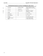
Page 18: ... to Tap 20 to 30 ohms Start to Finish 110 to 140 Ohms Polar Unit Operating Coil 290 320 Polar Unit Restraining Coil Maximum 12 16 ohms Minimum 9 12 ohms Resistor RC 41 44 ohms Tube Resistor R0 Total of 1 6 ohms Formed Resistor R1 0 131 ohms Rectifiers IN91 Germanium Diodes Indicating Contactor Switch 0 2 amp Tap 6 5 ohms 2 0 amp Tap o 15 ohms ...

Page 19: ...Type HCB 1 Pilot Wire Relay System 41 971 3M 19 THIS SPACE RESERVED FOR NOTES ...

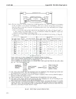
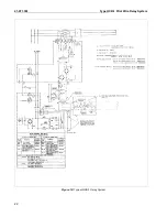
Page 20: ...41 971 3M Type HCB 1 Pilot Wire Relay System 20 Figure 9 HCB 1 Relay System Verification Tests ...

Page 21: ...Type HCB 1 Pilot Wire Relay System 41 971 3M 21 ...

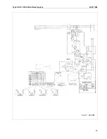
Page 22: ...41 971 3M Type HCB 1 Pilot Wire Relay System 22 Figure 10 Typical HCB 1 Relay System ...

Page 23: ...Type HCB 1 Pilot Wire Relay System 41 971 3M 23 Sub 15 4810D98 ...

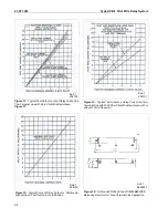
Page 24: ...cal Test Output vs Relay Current in a Two Terminal Line with 2000 Ohm Pilot Wire Resistance with or without 10 mfd Capacitor Figure 13 Typical Curve of Relay Output vs Positive Se quence Input Test Switch in Local Position Figure 14 Outline and Drilling Plan of S 290B664G65 Balancing Resistor for Three Terminal Line Application Sub 1 538103 Sub 1 538101 Sub 1 880A797 Sub 1 538102 ...

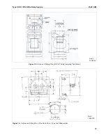
Page 25: ...ilot Wire Relay System 41 971 3M 25 Figure 15 Outline and Drilling Plan of HCB 1 Relay Insulating Transformer Figure 16 Outline and Drilling Plan of the Semi Flush Type Test Milliammeter Sub 1 184A739 Sub 2 13C5342 ...

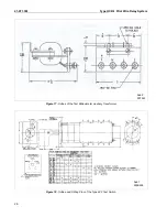
Page 26: ...1 971 3M Type HCB 1 Pilot Wire Relay System 26 Figure 17 Outline of the Test Milliammeter Auxiliary Transformer Figure 18 Outline and Drilling Plan of the Type W 2 Test Switch Sub 1 293B226 5D1523 Sub 2 ...

Page 27: ...Type HCB 1 Pilot Wire Relay System 41 971 3M 27 THIS PAGE RESERVED FOR NOTES ...

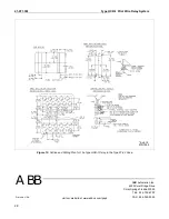
Page 28: ...57D7905 Printed in U S A ABB Automation Inc 4300 Coral Ridge Drive Coral Springs Florida 33065 TEL 954 752 6700 FAX 954 345 5329 ABB visit our website at www abbus com papd Figure 19 Outline and Drilling Plan for t he Type HCB 1 Relay in the Type FT 42 Case ...

Reviews: