41-971.3M
Type HCB-1 Pilot Wire Relay System
4
represent air gaps which are bridged by two adjust-
able magnetic shunts. The operating and restraint
windings are concentrically wound around a mag-
netic core. The armature is fastened to this core at
one end and floats in the front air gap at the other
end. The moving contact is connected to the free end
of a leaf spring.
2.4.
Restraint Taps
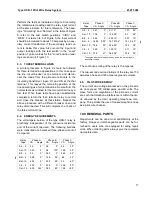
A set of restraint taps are located on the front of the
relay near the polar unit. These taps are the maxi-
mum and minimum restraint taps of the relay.
2.5.
INDICATING CONTACTOR SWITCH UNIT
(ICS)
The dc indicating contactor switch is a small clapper-
type device. A magnetic armature, to which leaf-
spring mounted contacts are attached, is attracted to
the magnetic core upon energization of the switch.
When the switch closes, the moving contacts bridge
two stationary contacts, bypassing the main relay
contacts. Also during this operation, two fingers on
the armature deflect a spring located on the front of
the switch, which allows the operation indicator tar-
get to drop. The target is reset from the outside of the
case by a push-rod located on the bottom of the
cover.
The front spring, in addition to holding the target, pro-
vides restraint for the armature, and thus controls the
pickup value of the switch.
3.0 OPERATION
The connection of the HCB-1 system of relays to the
protected transmission line is shown in Figure 10. In
such a connection, the relays operate for faults within
the line terminals but not for faults external to the pro-
tected transmission line. This is accomplished by
comparing the relative polarities of voltages at oppo-
site ends of the transmission line by means of a
metallic pilot-wire.
As shown in Figure 4, the composite sequence filter
of each HCB-1 relay receives three-phase current
from the current transformers of the transmission
line. The composite sequence filter of the HCB-1
converts the three-phase current input into a single-
phase voltage output, V
F
, of a magnitude which is a
function of the positive, negative and zero sequence
components of fault current. This voltage V
F
, is
impressed on the primary wiring of the saturating
transformer. The saturating transformer output volt-
age, V
S
, is impressed on the primary wiring of the
saturating transformer. The saturating transformer
output voltage, V
S
, is impressed on the primary wir-
ing of the saturating transformer. The saturating
transformer output voltage, V
S
, is applied to the relay
coils and to the pilot-wire through an insulating trans-
former. The saturating transformer and a zener clip-
per across its secondary winding serve to limit the
energy input to the pilot-wire.
During an external fault, assuming matched relays,
the magnitude of V
S
at both stations will be the
same. The relative polarities of the V
S
voltages will
be shown in Figure 4. Since the voltages add, most
of the current will circulate through the restraint coils
and the pilot-wire, with a minimum of operating coil
current. The relative effects of the operating and
restraint coil currents are such that the relay is
restrained.
During an internal fault, the relative V
S
voltages
reverse. Since the V
S
voltages now oppose each
other, most of the current flowing in the restraint coils
is also forced through the operating coils with a mini-
mum of current in the pilot-wire. This increase in
operating current overcomes the restraining effect
and both the relays operate.
Within limits, as defined in Figure 7 and under “Char-
acteristics,” all the relays will operate for an internal
fault regardless of the fault current distribution at the
various stations. The nominal pickup (total internal
fault current) of the relaying system is equal to the
minimum trip of a single relay multiplied by the num-
ber of relays. For example, if the pickup of each
relay, with the pilot-wire open, is 6 amperes, a two
terminal line system has a nominal pickup of 2 X 6 =
12 amperes.
3.1.
PILOT-WIRE EFFECTS
In Figure 4 it can be seen that a short-circuited pilot-
wire will short circuit the relay operating coils.
Depending on the location of the short, at least one
of the relays will fail to trip during an internal fault. If
Summary of Contents for HCB-1
Page 19: ...Type HCB 1 Pilot Wire Relay System 41 971 3M 19 THIS SPACE RESERVED FOR NOTES ...
Page 21: ...Type HCB 1 Pilot Wire Relay System 41 971 3M 21 ...
Page 22: ...41 971 3M Type HCB 1 Pilot Wire Relay System 22 Figure 10 Typical HCB 1 Relay System ...
Page 23: ...Type HCB 1 Pilot Wire Relay System 41 971 3M 23 Sub 15 4810D98 ...
Page 27: ...Type HCB 1 Pilot Wire Relay System 41 971 3M 27 THIS PAGE RESERVED FOR NOTES ...


