41-971.3M
Type HCB-1 Pilot Wire Relay System
8
Sub 5
183A062
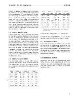
Figure 5: Polar Unit Permanent Magnet Flux Paths
4.5.
PILOT-WIRE REQUIREMENTS
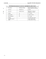
The relays should not be applied with pilot-wire
series resistance or shunt capacitance exceeding the
following values:
R
L
=
series loop resistance in ohms.
C
S
=
total shunt capacitance in microfarads.
(Total wire to wire capacitance)
Where the shunt capacitance exceeds the above
amount, it may be feasible in some cases to provide
shunt reactors to compensate for the excessive
capacitance. The amount of capacitance which can
be compensated is limited and varies depending
upon the magnitude of the pilot-wire distributed
effect.
A shielded, twisted pilot-wire pair, preferably of #19
AWG or larger, is recommended; however, open
wires may be used if they are frequently transposed
in areas of exposure to power circuit induction. The
voltage impressed across either insulating trans-
former (H1-H4 Terminals) as a result of induction or a
Table 4
Insulating Transformer Rate
No. of
Relays
4/1
6/1
R
L
C
S
R
L
C
S
2
2000
1.5
4500
0.33
3
500/LEG
1.8
1000/LEG
0.75
rise in station ground potential, should be less than
7.5 volts to prevent undesired relay operation.
For three-terminal applications, the loop resistance of
all legs of the pilot-wire must be balanced within 5
percent, with variable resistors. The pilot-wire resis-
tance to be balanced is divided by 16 and 36 for the 4
to 1 and 6 to 1 ratio insulating transformers respec-
tively, since the balancing resistors are located on
the relay side of the insulating transformers.
Induced voltages and rises in station-ground poten-
tial may be handled by the following means:
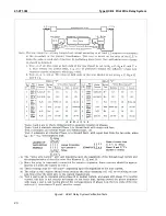
Figure 6: Typical Curves Showing the Effect of the Pilot-
wire on Minimum Trip Current, Two-Terminal Line
(Maximum Resistant Tap). Insulating Transformer 4/1 ratio
Sub 1
619594
N
N
S
S
N
N
S
S
Moving Contact
Armature
Permanent
Magnet
BALANCED AIR GAPS
UNBALANCED AIR GAPS
N
Additional
Flux Path
Shunt
Summary of Contents for HCB-1
Page 19: ...Type HCB 1 Pilot Wire Relay System 41 971 3M 19 THIS SPACE RESERVED FOR NOTES ...
Page 21: ...Type HCB 1 Pilot Wire Relay System 41 971 3M 21 ...
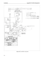
Page 22: ...41 971 3M Type HCB 1 Pilot Wire Relay System 22 Figure 10 Typical HCB 1 Relay System ...
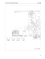
Page 23: ...Type HCB 1 Pilot Wire Relay System 41 971 3M 23 Sub 15 4810D98 ...
Page 27: ...Type HCB 1 Pilot Wire Relay System 41 971 3M 27 THIS PAGE RESERVED FOR NOTES ...


