23
3.2.4 Transition from Independent to Power Conditioning mode
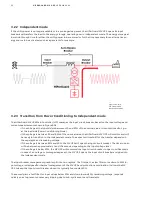
As soon as the input voltage returns to the nominal level, the MV UPS starts the transition from the Independent
to the Power Conditioning mode. A “trust period” of two seconds before the transition assures that the input volt-
age is stable, avoiding unnecessary breakers operations.
During this process, the MV UPS will synchronize the output voltage to the input voltage. While the MV UPS is in
“synchronizing state”, if a power quality event reoccurs, the MV UPS will return to the Independent mode.
When the MV UPS output voltage is phase-locked with the input voltage, the MV UPS commands the input circuit
breaker to close. After closing the input circuit breaker, the MV UPS transfers the load to the utility while it con-
trols the voltage phase across the reactor to make sure the voltage is being conditioned to the nominal level at the
load side.
—
Figure 3.04: Three
phase under/over
voltage input breaker
management graph.
3.2.5 Transition from Independent to Power Conditioning mode (upstream gener-
ator adaptive walk-in)
Frequently diesel or gas generators are connected to the MV UPS input as secondary power supplies in case of ex-
tended duration power outages. In such cases, the MV UPS assumes change-over to upstream generator bus in
frequency and voltage reference mode, often known as Island Forming. The MV UPS has a single digital input
which indicates if it is connected to a grid or a generator. When supplied by a generator, specific tunings are
made.
As soon as the generator output connected to the MV UPS input reaches nominal voltage and frequency level, the
MV UPS starts the transition from the Independent to the Power Conditioning mode. The hand-over process of
transferring the load from the MV UPS (using the energy stored in the batteries as a power source) to the genera-
tor is called adaptive walk-in.
The MV UPS achieves maximum generator walk-in speed using a frequency droop & clamp approach. When the MV
UPS detects that the input voltage and frequency are according to the specification, and following a two second
trust period, the input breaker is closed.
The MV UPS attempts to transfer the load to the generator by lowering its frequency at a rate of 1 Hz-per-second
but clamps the frequency droop to an error of 2% (configurable). The load sharing starts by the MV UPS trying to
load the generator. If the generator droops down to the threshold threshold (2% of the system nominal fre-
quency), then the MV UPS holds the existing power level until the generator can catch up.
Summary of Contents for HiPerGuard MV UPS
Page 58: ...58 HIPERGUARD MV UPS USER MANUAL Figure 7 04 Pages map ...
Page 84: ......


