44
H I PE RG UA R D M V U PS
US ER M A N UA L
—
6.2 Medium voltage connections to MVM enclosure
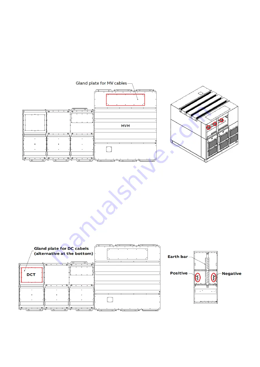
The medium voltage input and output cables coming from the switchgear are connected to the MV UPS on the top
of the MVM enclosure. There is a removable cable gland plate available on the top of the enclosure to accommo-
date the cables and avoid the ingress of extraneous objects. The opening and the input and output terminals are
located on the rear side of the MVM. On the opposite side, there is a removable cable gland plate destined for the
optional connection to the site midpoint. Figure 6.01 shows the location of the cable gland plates and terminals.
—
Figure 6.01: Gland
plate (top view) and
connections for the
medium voltage cables
(MVM enclosure)
—
6.3 Energy storage connections to DCT enclosure
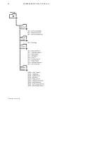
The DC cables coming from the energy storage are connected to the MV UPS on the top or bottom (model depen-
dent – please refer to the product type code) of the DCT enclosure. There is a removable cable gland plate to ac-
commodate the cables and avoid the ingress of extraneous objects.
—
Figure 6.02: Gland
plate (top view) and
connections for the DC
cables (DCT enclo-
sure - front virew).
Summary of Contents for HiPerGuard MV UPS
Page 58: ...58 HIPERGUARD MV UPS USER MANUAL Figure 7 04 Pages map ...
Page 84: ......


