53
—
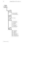
Figure 6.09: Fiber
optic interface MV UPS
to MV Switchgear .
—
6.6 Modbus TCP/Web interfaces
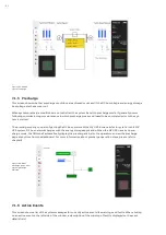
The Modbus TCP and web interfaces can be physically accessed through the internet coupler XF1. The connection
point is located in the APS enclosure (RJ45 socket). Figure 6.10 shows the location of internet coupler XF1, in the
APS enclosure.
—
Figure 6.10: Ethernet
interface XF1, XF2, XF3,
and XF4 (reserved).
—
6.7 Communication between MV UPS units in
parallel configuration
It is possible to connect two or more HiPerGuard MV UPS units in a parallel configuration. The medium voltage in-
put and output connections of the group are paralleled via the medium voltage switchgear. This enables the MV
UPS system total output power capacity to be increased according to the number of units in parallel, and to
achieve redundancy in the event of a fault with one of the units.
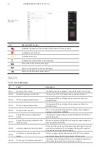
To achieve the required load sharing and fault handling in the paralleled group, it is necessary to set up a commu-
nications link between the Main Controllers of each of the paralleled units. The APS enclosure of each MV UPS unit
has Ethernet has Ethernet couplers XF2, XF3 installed (Figure 6.10), to enable setup of the parallel machine com-
munications network. Refer to Figure 6.11.
Summary of Contents for HiPerGuard MV UPS
Page 58: ...58 HIPERGUARD MV UPS USER MANUAL Figure 7 04 Pages map ...
Page 84: ......


