2
9AKK107991A0084 EN Rev. A
| HM/A 1.1, HM/A 2.1
—
TECHNICAL DATA
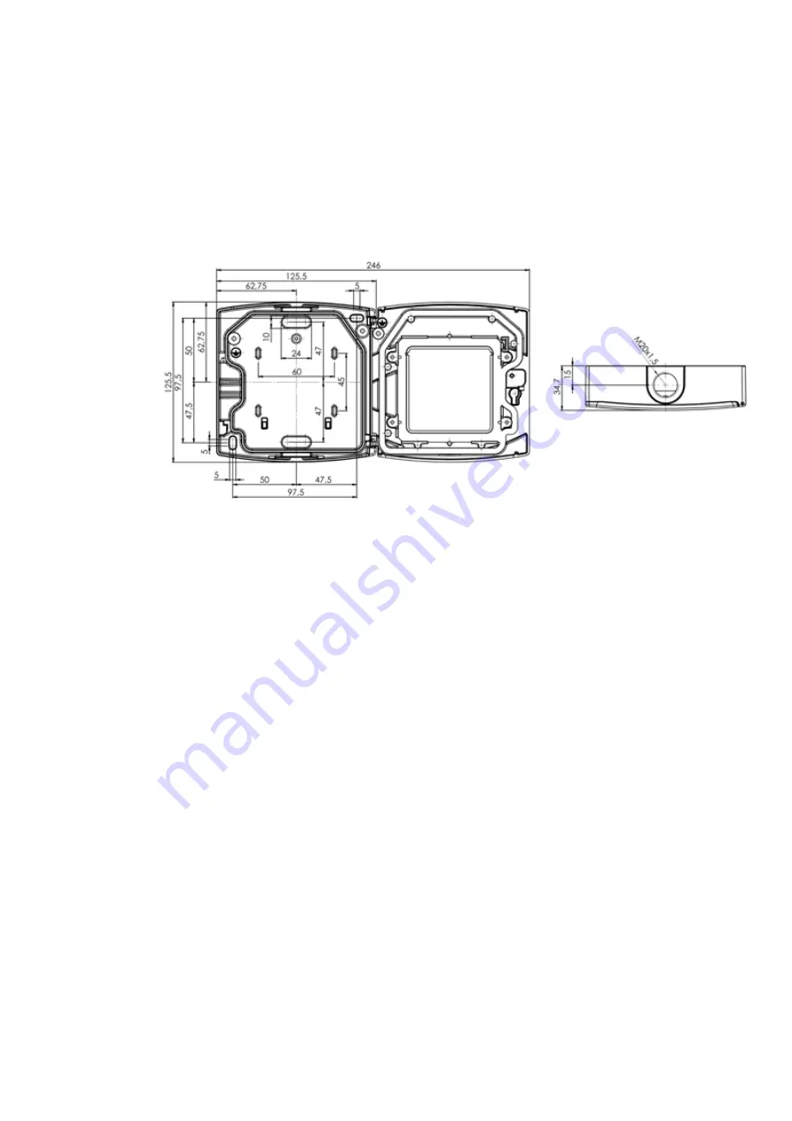
Dimension drawing
Mounting
The Manual Call Points are mounted at an easily visi-
ble location at a height of 1.4 m +0.2 m / -0.4 m.
You can find information about this in the DIN VDE
0833-2 standard and in the BHE guideline for house
alarm systems – type A. Mount the housings using
suitable oval-head screws with washers.
Countersunk head screws must not be used.
The dimension drawing shows the fixing dimen-
sions, the overall dimensions and the predetermined
breaking points for FM cable entry.
The upper and lower predetermined breaking points
on the rear wall of the Manual Call Point housing can
be opened to permit direct mounting on an FM box
or hollow-wall box (see dimension drawing; horizon-
tal distance 60 mm). Both SM and FM cable entries
are available for the cabling.


