HM/A 1.1, HM/A 2.1 |
9AKK107991A0084 EN Rev. A
3
—
TECHNICAL DATA
Connection
—
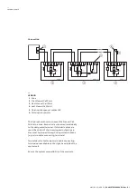
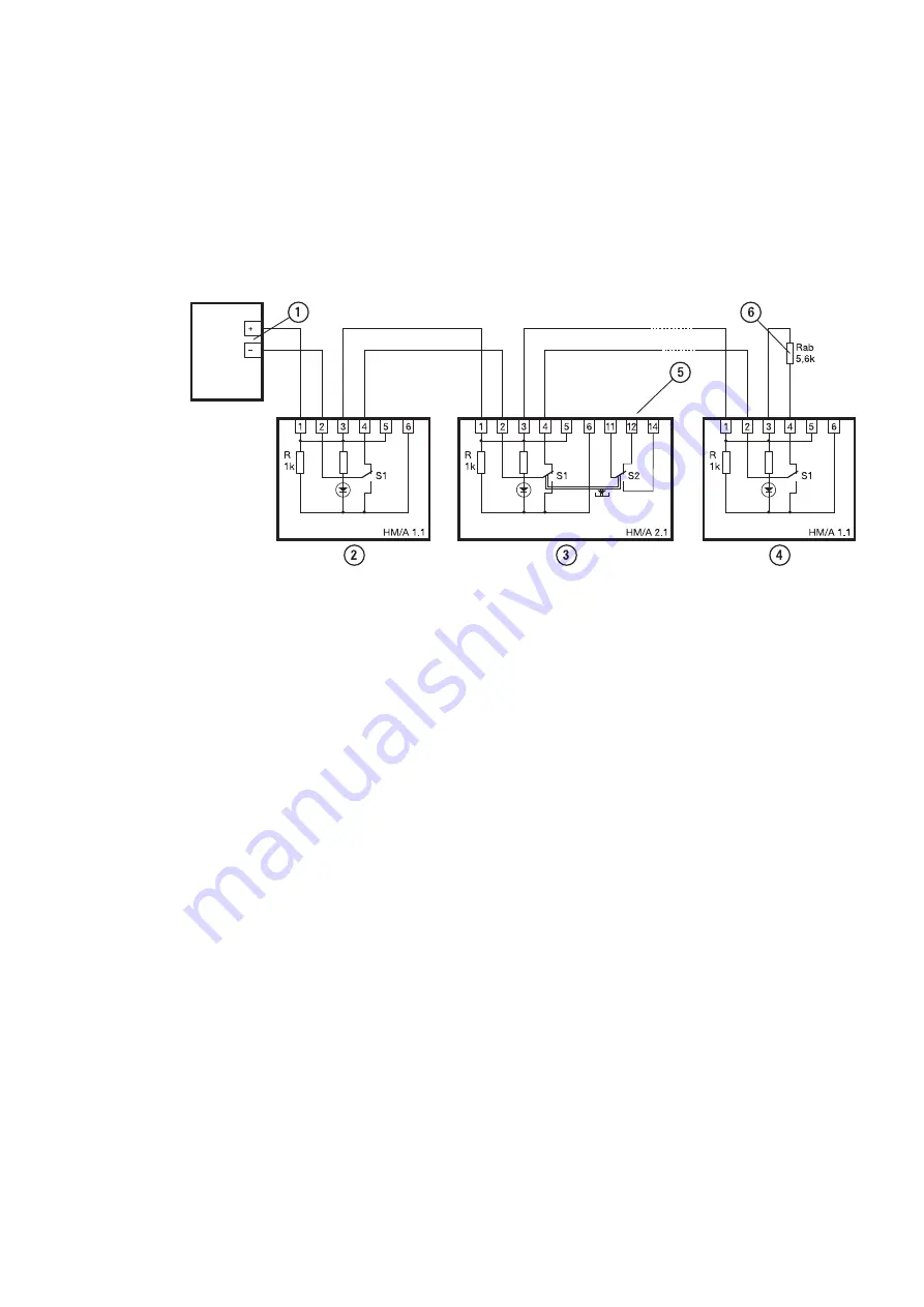
LEGEND
1
Zone
2
First Manual Call Point
3
Next Manual Call Point
4
Last Manual Call Point
5
Floating changeover contact S2
6
Termination resistor
The figure shows how to connect the Manual Call
Points to a zone. Each wire is connected individually
to the designated terminal. If shielded cables are
used, the shield of the incoming and outgoing ca-
bles must be looped through using suitable means
(e.g. micro cable connecting terminals).
Two holders for fastening micro cable connecting
terminals are available on the right-hand side of the
control unit.
Ensure the system compatibility of the products.


