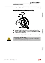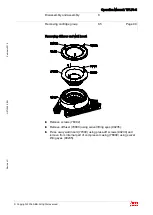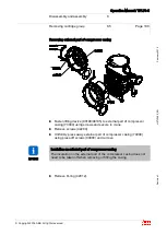
Operation Manual / TPL76-C
Removal and installation
7
Remove the turbocharger
7.2
Page 86
© Copyright 2016 ABB. All rights reserved.
Febr
uar
y 2016
H
ZT
L2485_
EN
R
ev
is
ion
C
Remove the turbocharger
7.2
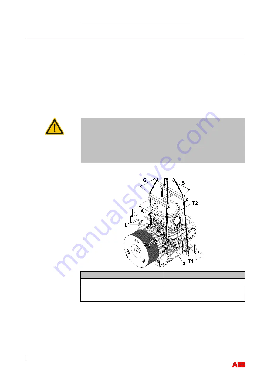
A suitable suspension device (as illustrated) must be used when
removing and installing the turbocharger. The suspension device is not
supplied by ABB Turbo Systems.
Disconnect all gas, air and oil lines in accordance with engine builder’s
instructions.
CAUTION
Oil orifice plates
An orifice plate for adjusting the oil pressure is fitted in each of the two
oil inlet channels in the bearing casing. When the cartridge group, the
bearing casing or the turbocharger is fitted to the engine, it must be
ensured that the orifice plates that are specified for the turbocharger
have been installed in the two oil inlet channels.
Check correct installation of oil orifice plates.
Suspension dimension
Distance in [mm]
A
860
B
1210
C
800
Use the two suspension lugs (L1, L2) on the bearing casing (observe the
marking on the insulation).
The two suspension lugs on the foot at the turbine end (T1, T2) serve to
align the turbocharger horizontally.
7.2


