Operation Manual / TPL65-A32 / -A33 / -A36 + TPL69-A32 / -A33
8 Disassembly and assembly / 8.8 Dismantling and fitting nozzle ring
at turbine end
© Copyright 2018 . All rights reserved.
HZTL2498_EN
Revision C
April 2018
u
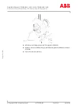
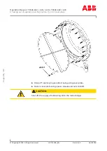
Loosen and remove the remaining screws (61044) and Verbus Ripp®
washers (61043) from the gas inlet casing flange (61001).
u
Pull gas inlet casing complete with nozzle ring just far enough away
from gas outlet casing that nozzle ring (56001) can be lifted away.
u
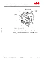
Loosen the hexagon nuts (90178) on the studs.
u
Fully withdraw the gas inlet casing and remove it.
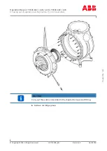
CAUTION
When setting down the gas inlet casing to one side, use suitable under-
lays and take care not to damage the angles of the insulation.
u
Remove (optional) gasket (61050).
Fitting the nozzle ring
If provided:
u
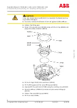
Insert (optional) gasket (61050) into groove in gas inlet casing
(61001).
u
Align gas inlet casing and secure using hexagon nuts (90178) on studs
(90177) .
u
Insert nozzle ring (56001) and position it.
u
Brush screw threads (61044) with high temperature grease.
u
Fit the gas inlet casing flange to the gas outlet casing using screws
(61044) and Verbus Ripp® washers (61043), then tighten it.
u
Remove the hexagon nuts (90178) from the studs (90177).
u
Replace the studs (90177) with hexagon-head screws (61044) and Ver-
bus Ripp® washers (61043).
u
Remove lifting gear from gas inlet casing (51001).
u
Secure the insulation to the gas inlet casing (51001).
Page
94
/
118


