background image

Operation Manual

ABB  Turbocharging

Type

TPL85-B14

HT842305

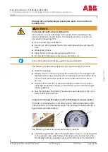
n

Mmax

203

t

Mmax

550

n

Bmax

193

t

Bmax

520

1/s

°C

12000

36

100

100

Year

2020

Application according to

the Operation Manual

kg 

HZTL2491 English

TPL85-B14

Original Operation Manual

Summary of Contents for HT842305

Page 1: ...ABB Turbocharging Type TPL85 B14 HT842305 nMmax 203 t Mmax 550 nBmax 193 t Bmax 520 1 s C 12000 36 100 100 Year 2020 Application according to the Operation Manual kg HZTL2491 English TPL85 B14 Original Operation Manual ...

Page 2: ...Replacement intervals of components depends on the load profile turbine inlet temperature suction air temperature and turbocharger speed In case the operation conditions differs significantly from what is considered to be normal for the cur rent application it is recommended to contact ABB for a re calculation of replacement intervals Frequent load alterations high temperatures and high speed lowe...

Page 3: ... Safety instructions 15 2 5 Warning plates on the turbocharger 16 2 6 Safe operation and maintenance 16 2 7 Hazards during operation and maintenance 19 2 8 Periodic checking of the pressure vessel 24 2 9 Lifting loads 24 3 Start up 26 3 1 Oil supply 26 3 2 Inspection work 29 3 3 Commissioning after taking out of operation 31 4 Operation 32 4 1 Noise emissions 32 4 2 Admissible air inlet temperatur...

Page 4: ...ncer casing 86 8 4 Removing and installing the filter silencer 90 8 5 Axial clearance 92 8 6 Removing internal part of compressor casing 93 8 7 Removing gas inlet casing 97 8 8 Fitting gas inlet casing 99 8 9 Fitting internal part of compressor casing 100 8 10 Dry cleaning device 103 8 11 Table of tightening torques 106 9 Short term turbocharger shut down 108 9 1 Possibilities for emergency repair...

Page 5: ... Systems and to use it as intended It provides important information in order that the turbocharger can be operated safely correctly and efficiently This Operation Manual complements and expands existing national reg ulations concerning work safety and accident prevention Target group This Operation Manual is intended for engineers and qualified mechan ics who are responsible for operating the eng...

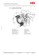
Page 6: ...All rights reserved HZTL2491_EN Revision C August 2018 1 2 Layout and function 1Filter silencer 7Nozzle ring 2Radial plain bearing 8Turbine wheel 3Thrust bearing 9Bearing casing 4Radial plain bearing 10Diffuser 5Gas outlet casing 11Compressor wheel 6Gas inlet casing 12Compressor casing Page 4 123 ...

Page 7: ... the compressor casing 12 The rotor runs in two radial plain bearings 2 4 which are located in the bearing casing 9 between the compressor and the turbine The axial thrust bearing 3 is at the compressor end The plain bearings are connected to a central lubricating oil duct which is normally supplied by the lubricating oil circuit of the engine The oil out let is always at the lowest point of the b...

Page 8: ... in stallation fitting disassembly removal operating maintenance ser vicing and repair conditions specified by the manufacturer Disposal reg ulations set down by local authorities must be observed Perfect condition The turbocharger may be installed only when in technically perfect condi tion while observing the instructions given in the engine builder s manual It may be used only for the intended ...

Page 9: ...red every 6 months u Open the package u Remove the VCI corrosion protection emitter from the package and replace it with a new identical VCI corrosion protection emitter New VCI corrosion protection emitters can be obtained at www brano pac com u Dispose of the old VCI corrosion protection emitter in an environ mentally compatible manner professionally and in accordance with local regulations u Se...

Page 10: ...rk steps must be performed by an ABB Turbocharging Service Station Inspect the components Exchange the desiccant agent Repackage the components NOTICE Replacement components ready for operation If the 70 display field of the hygrometer 02 has not changed colour and the package is undamaged the replacement turbocharger or re placement cartridge group can be placed into operation without any prior t...

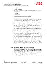
Page 11: ...n and wearing of personal protective equipment NOTICE The manner in which personnel work on and with the turbocharger with regard to safety and risks is to be checked on a regular basis in accord ance with the Operation Manual u The turbocharger must be shut down immediately in the event of modifications affecting safety or of corresponding operating beha viour by stopping the engine The fault sho...

Page 12: ...tence of personnel The turbocharger must only be operated and serviced by trained and au thorised personnel Basic mechanical training is a prerequisite Design variants This document is valid for different design variants of turbochargers There may be sections and descriptions of components that are not rel evant for a specific turbocharger variant ABB Turbocharging Service Stations will be happy t...

Page 13: ...duct Definition of mandatory signs Mandatory signs show the protective equipment to be worn for a task The mandatory signs are described in chapter Safety and must be com plied with Definition of caution warning The caution and warning signs are described in the chapter Safety ABB Turbo Systems In this document ABB Turbo Systems Ltd is abbreviated to ABB Turbo Systems Official ABB Turbo Systems Se...

Page 14: ...e agreed with the enginebuilder 02 Turbocharger operating limits during operation Recommended replace ment intervals for tur bocharger components 03 Replacement interval for plain bearings in 1000 h 04 Replacement interval for compressor in 1000 h 05 Replacement interval for turbine in 1000 h Further information 06 Part number for customer 07 Designation of special design 08 Turbocharger weight in...

Page 15: ...d tMmax normally apply only when running at overload 110 during trials on the engine test bed Operation above nMmax and tMmax is not permit ted Non observance of the recommended replacement intervals increases the risk of unpredictable component failures 1 7 2 Positions of the rating plates A rating plate is attached to the turbocharger foot one on the left and one on the right On turbochargers wi...

Page 16: ...ence of insufficient observance of the safety instruc tions are the consequence of unsatisfactory and improper execution of maintenance and inspection work The operating company is responsible for access to the turbocharger as well as the organisational measures that regulate the safe handling of the turbocharger by its personnel All instructions contained in this chapter must be observed for safe...

Page 17: ...Ear protection 2 4 Definition of Safety instructions The following symbols and terms used in this manual concern safety or refer to possible hazards WARNING Definition of warning Serious personal injuries and even accidents with fatal consequences may occur if work and operating instructions marked with this symbol and the word WARNING are either not followed or not followed pre cisely u Warning s...

Page 18: ... the insulation This is the responsibility of the engine builder 2 6 Safe operation and maintenance The instructions specified in this section are for the safety of personnel Together with the instructions in the Hazards during operation and maintenance section they allow the user to safely use the turbocharger Work safety and work area safety WARNING Risk of falling There is the risk that someone...

Page 19: ...s not damaged u Remove combustible objects and substances out of the range of fly ing sparks u Cover all connections on the turbocharger so that no foreign objects can get into the turbocharger u Wear personal protective equipment PPE for welding operations Safety during start up commissioning and operation u Before starting work carry out visual inspection of working area u Remove any obstacles a...

Page 20: ...rating personnel about all service and repair work before beginning u Before opening a cover or removing a protective device on a tur bocharger the engine must be switched off and the turbocharger must have come to a standstill u Ensure that the supply of oil is interrupted especially with an external oil supply u Put the engine into operation only after all parts have been refitted properly CAUTI...

Page 21: ...rbocharger in accordance with instructions u During maintenance work secure the rotor against unintentional ro tation Mechanical hazards when working on the turbocharger During maintenance work various risks can occur through the improper handling of components through the non observance of work instruc tions due to inadequate care or as a consequence of insufficient train ing WARNING Mechanical h...

Page 22: ...ve 85 dB A always wear ear protection Wear ear protection Hazards due to hot surfaces and substances During operation turbocharger surfaces and attached parts as well as operating materials lubricating oil become hot The surface temperat ure is dependent on the effectiveness of the insulation being used The temperature can become high enough so that it falls into ranges where burns are possible WA...

Page 23: ...charger surfaces is compuls ory Wear safety gloves to protect against thermal hazards Hazards due to operating and auxiliary materials Operating and auxiliary materials are substances used for operation or the execution of maintenance work Oils greases coolants cleaning agents and solvents acids etc can be regarded as hazardous materials Operating and auxiliary materials can be combustible and eas...

Page 24: ...ontamination of the ground and water due to improper disposal can lead to environmental damage u Handle operating and auxiliary materials carefully u Heed the instructions for use safety data sheets and hazard notices on the containers of the operating and auxiliary materials u Wear appropriate protective clothing u Avoid inhalation and contact with the skin u Ensure that the work space is adequat...

Page 25: ... area u Take particular care when removing old insulating materials u Dispose of insulating materials properly and in an environmentally compatible way in accordance with applicable local regulations Wear safety goggles Wear a respiratory mask to protect against dusts Wear safety gloves to protect against chemical hazards u Use only suitable non combustible insulating materials u Ensure that the w...

Page 26: ...sels must be observed The operating company is responsible for the safe operation of the pressure vessel WARNING Danger due to pressure vessels The operating company must make sure the pressure vessels are in proper working condition and monitor them Necessary repair or main tenance work must be carried out without delay and the required safety precautions must be taken u Pressure equipment must n...

Page 27: ...le loading u Fasten turbocharger assemblies components as described in re spective handling steps u Before attaching slings allow turbocharger components to cool down maximum 80 C u Use suitable protection at sharp edges u Completely screw in assembly fitting devices without fail so that they cannot work loose during use u Use assembly fitting devices only for applications described u Make sure re...

Page 28: ...ions is an important prerequisite for trouble free turbocharger operation The turbocharger is normally lubricated with oil from the engine oil cir cuit NOTICE With regard to the oil supply please observe the engine builder s spe cifications for lubricating oil selection oil change intervals oil filtration oil pressure and oil temperature Oil filtration A lubricating oil filter with a mesh size of ...

Page 29: ...Temporarily permissible 1h alarm 0 6 0 8 Permissible oil pressure range for normal opera tion 0 8 2 5 Permissible oil pressure range during engine warm up phase 0 8 4 0 Separate lubricating sys tem Kinetic viscosity 12 170 cSt Oil pressure bar Impermissible oil pressure range emergency shutdown without time lag 0 0 0 9 Temporarily permissible 1h alarm 0 9 1 1 Permissible oil pressure range for nor...

Page 30: ...the outlet is mainly dependant on Lubricating oil temperature and pressure at the oil inlet Engine load and turbocharger speed Exhaust gas temperature The maximum admissible oil temperature at the outlet is listed in the fol lowing table The specified oil outlet temperature is to be considered as alarm value for the turbocharger operation and must be monitored ac cording to the current regulations...

Page 31: ...ntaminated oil Particles of dirt and solid matter in the oil can cause serious damage to the machine or property u During initial commissioning and after all service work the complete lubricating system must be flushed thoroughly with warm oil u When running in the engine and after all service work on the lubricat ing system special running in filters must be used u Check oil pressure in oil suppl...

Page 32: ...temperature in front of and behind turbine u Measure air temperature in front of and behind compressor The measured values must be compared with the values in the accept ance test report while taking different operating conditions into ac count NOTICE Lubricants and pastes used during assembly of the turbocharger li quefy or vaporise and might escape as an oily liquid in the first few hours after ...

Page 33: ...ct before gas inlet and after gas outlet u Inspect exhaust gas duct line in front of and after turbine for any combustion deposits foreign matter or residual water Clean and re move u Inspect air supply line or filter silencer for any foreign matter Clean and remove u Start up turbocharger oil circulation system at engine end u Prepare turbocharger for operation as instructed in section Inspec tio...

Page 34: ...urbocharger The highest sound pressure level of emissions1 reaches a maximum of 105 dB A near the filter silencer and over the entire speed range The following prerequisites must be fulfilled on the turbocharger in or der to observe this limit value Fitted air inlet system All standard noise reducing measures have been taken2 The bellows at the air outlet have been perfectly insulated acoustic all...

Page 35: ...r inlet temperature must be between 40C 45C 4 3 Servicing work Service work to be carried out during operation involves visual checks monitoring measuring inspection work and functional checks It is then possible for changes to the turbocharger to be identified and rectified In this way it can be ensured that the turbocharger remains in full work ing order CAUTION Service intervals Service work on...

Page 36: ...e arranged with ABB Turbo Sys tems NOTICE Service inspection after 5 years To prevent age and stoppage related machine damage an inspection by an ABB Turbocharging Service Station is recommended at the latest 5 years after the last service 4 3 1 Service work every 25 50 hours u Visual inspection for air exhaust gas water and oil leaks u Record operating data and enter it in the engine logbook u Cl...

Page 37: ...facturer s engine logbook Engine performance and speed Air intake temperature Exhaust gas temperature in front of and behind the turbine Pressure of charge air Pressure drop in charge air cooler Lubricating oil pressure and lubricating oil temperature If provided Air temperature behind compressor and charge air cooler Turbocharger speed Pressure loss in air filter 4 3 3 Servicing work according to...

Page 38: ... or damage Optionally this inspection can be carried out after removing the gas inlet casing u Refit the compressor casing internal part u Refit the filter silencer 4 3 5 Service work every 36 000 hours The replacement of bearing parts and the inspection and assessment of the rotor must be carried out by an ABB Turbocharging Service Station u Remove the filter silencer u Clean the filter silencer ...

Page 39: ... These intervals can be found on the turbocharger rating plate Non rotating components Depending on the system specific operating conditions a distinction is made between the replacement interval for the bearing parts and the replacement interval for those non rotating components that are exposed to hot gases Decisive in this respect are various influencing parameters which can drastically shorten...

Page 40: ...intervals h Rotor components See the data on the rating plate Bearings See the data on the rating plate NOTICE Information about replacement intervals The specified values are only guide values and not guaranteed They can vary significantly due for example to inadequate servicing frequent emergency shutdowns and the use of fuel or lubricating oil of inferior quality 4 5 Speed measurement A speed m...

Page 41: ...eration 4 5 Speed measurement Copyright 2018 All rights reserved HZTL2491_EN Revision C August 2018 Part number Description 42047 Screw plug 86505 Speed sensor 86515 Cable connector for 86505 86526 F I converter 86528 Tachometer Page 39 123 ...

Page 42: ...wing steps must be carried out u Reduce engine performance immediately until the highest turbochar ger speed no longer exceeds 70 of nBmax u If the engine cannot be stopped continue to run at this reduced en gine performance or turbocharger speed u If the turbocharger surges continuously engine performance must be reduced further u Measure the temperatures in the air and gas lines to and from the ...

Page 43: ... stop the engine u Switch off the lubricating oil supply to the turbocharger u Disconnect the cable connector from the speed sensor u Screw out defective speed sensor u Screw in a new speed sensor to the stop u Observe the tightening torque see the table of tightening torques in the chapter entitled Disassembly and assembly NOTICE Sealing of the speed sensor The speed sensor is designed with a sea...

Page 44: ... at the filter silencer The measurement can be used for the following purposes To measure the correction factor for calculating the turbocharger ef ficiency during the engine acceptance test The use of a filter mat on the filter silencer can cause a loss of pres sure A significant pressure loss indicates an increase in dirt build up in the filter material 4 6 1 U tube manometer on filter silencer ...

Page 45: ...laps are installed upstream of the gas inlet and downstream of the air outlet of the turbocharger The lubricating oil supply of the shut down turbocharger must not be switched off because of engine vibration To ensure that there are no oil and gas leaks this turbocharger must be supplied with sealing air A turbocharger may only be shut down or switched on if the engine is stationary or running dea...

Page 46: ...CAUTION Flexible turbocharger cut out Improper manipulations can result in inadmissible turbocharger speeds which can lead to serious damage to property with grave con sequences u The air outlet flap and gas inlet flap must be completely open during normal operation u During cut out operation the air outlet flap and gas inlet flap must be completely closed NOTICE Contamination with closed flaps To...

Page 47: ...checks and clean ing to ensure that the turbocharger and its attached units function trouble free The external condition and how dirty the cleaning points specified in this chapter are must be established by visual checks at the spe cified intervals The safety precautions must be observed during all maintenance and servicing work The cleaning points described in the following are Filter silencer C...

Page 48: ... C August 2018 5 2 Cleaning the filter silencer 5 2 1 Filter silencer with tension band 81265 Filter ring if provided 81266 Cover grid 81270 Tension band 81136 Absorption segment 81271 Lock 81137 Sheet metal covering 81268 Connecting strip 81135 Filter silencer body EInsert unit absorption segment sheet metal covering fitted Page 46 123 ...

Page 49: ... tension bands 81270 at the locks 81271 and remove them along with the cover grids 81266 and connecting strips 81268 NOTICE If the cleaning medium vessel is attached to the filter silencer option depends on type of turbocharger the water injection pipe must first be removed at one insert unit E see also the following section Disas sembling the cleaning pipe u Pull out insert units E bend open shee...

Page 50: ...he insert units E into the slot guides in the filter silencer body 81135 NOTICE If the cleaning medium vessel is attached to the filter silencer option depends on type of turbocharger the water injection pipe must first be removed at one insert unit E see also the following section Disas sembling the cleaning pipe u Fit cover grids 81266 and connecting strips 81268 on the filter si lencer body 811...

Page 51: ...yright 2018 All rights reserved HZTL2491_EN Revision C August 2018 5 2 2 Removing installing the cleaning line Disassembling the cleaning pipe u Disconnect feed pipe 02 from injection pipe 01 and remove pipe connector from feed pipe u Withdraw feed pipe 02 from guide tube 03 Page 49 123 ...

Page 52: ...e u Hammer guide tube 03 free from peen fixing using a bolt diameter 16 mm and withdraw it Replace damaged parts of the complete cleaning pipe with original parts from ABB Turbo Systems Fitting complete cleaning pipe u Refit guide tube 03 and peen fix it after putting insert units E in place u Fit feed pipe 02 and screw onto injection pipe 01 using connector Page 50 123 ...

Page 53: ...rved HZTL2491_EN Revision C August 2018 5 3 Changing the filter strip on the filter silencer casing This chapter is only applicable to turbochargers with a filter silencer cas ing The filter strip 81265 is replaced when a filter silencer is fitted u Dismantle the circumferential part 9 u Open the lock for the filter strip 81265 Page 51 123 ...

Page 54: ...ion C August 2018 u Secure a new filter strip 81265 so that it overlaps the filter strip be ing replaced u Pull the old filter strip until the new filter strip is wound completely around filter silencer u Loosen the connection between the new and old filter strips u Fasten the newly fitted filter strip 81265 and then refit the circum ferential part 9 Page 52 123 ...

Page 55: ...w channels if salt oil mist exhaust gas or dust are sucked in with the air Consequences of contamination Impaired compressor efficiency Higher exhaust gas temperatures Increased fuel consumption Increased rotor unbalance Periodic cleaning of the compressor during operation prevents or delays any major increase in contamination It does not however replace the regular service work during which the t...

Page 56: ...ont of the compressor wheel through an injection pipe fitted in the fil ter silencer The water does not act as a solvent but the contamination deposit is re moved by the mechanical impact of the droplets This is a very suitable process provided that the degree of contamination is not too high CAUTION Corrosion and deposits when cleaning Damage and impairment of turbocharger parts due to salt water...

Page 57: ...gine load 25 85 w If the engine compartment temperature is less than 0 C during wet cleaning of the compressor precautionary measures must be taken to prevent ice formation u Start cleaning cycle according to following description Wet cleaning operation with XC3 Operating procedure for compressor wet cleaning with XC3 Operating the water pres sure vessel u The operating state prerequisites for com...

Page 58: ...After cleaning wait at least 5 minutes to allow turbocharger to dry NOTICE If the cleaning operation is not satisfactory it may be repeated up to two times If the cleaning result is still not satisfactory after three attempts and the engine values are also unsatisfactory we recommend that you have the turbocharger inspected and cleaned by an official ABB Turbochar ging Service Station Cleaning par...

Page 59: ...t be met w Engine load 25 85 w If the engine compartment temperature is less than 0 C during wet cleaning of the compressor precautionary measures must be taken to prevent ice formation u Start cleaning cycle according to following description Wet cleaning operation with XC4 Procedure for compressor wet cleaning with XC4 01Cleaning medium vessel 02Pipe 03Injection pipe 04Cleaning instructions 05Co...

Page 60: ...ressor Product Contents of water vessel dm3 TPL85 B 3 0 5 5 Cleaning turbine blades and nozzle ring in operation Combustion of heavy fuel oil in diesel engines causes soiling of the tur bine blades and nozzle rings of the turbochargers Soiling increases with time so that regular and properly performed cleaning is important to remove the accumulated deposits The exhaust gas temperature downstream o...

Page 61: ...Depending on the composi tion of the contamination the individual effects with their different levels of intensity have a varying influence on the cleaning result Erosion The dirt is removed by the mechanical action of the impacting water droplets Solubility Water solubility of the contamination deposits in water Thermal shock Spalling of contamination due to temperature difference CAUTION Corrosi...

Page 62: ... PrerequisitesTPL A C Operating state prerequisites for wet cleaning turbine and nozzle ring CAUTION Reduced service life of the components Failure to comply with the minimum stabilisation time before cleaning the prescribed turbine inlet temperatures and the drying time after cleaning significantly reduces the expected service life of the compon ents u Comply with the cleaning parameters given in...

Page 63: ... the engine and the tem perature following the engine cylinder and exhaust valve rises Operating state prerequisites for wet cleaning In order to be able to carry out a satisfactory cleaning process that has been tested and is recommended by ABB Turbo Systems the following prerequisites must be met w After an engine start up or during operation the engine performance level must be adjusted until t...

Page 64: ...m w Before cleaning the Operating state prerequisites for wet cleaning must be met u Check that the water supply 1 is open and safeguarded and that it is also connected to the regulating valve 2 before the turbocharger u Set drain cock 9 of drain pipe 8 on gas outlet casing to Position 1 and check whether exhaust gas escapes u Quickly open regulating valve 2 until manometer 3 indicates follow ing ...

Page 65: ...rbine end These are caused by the turbine touching the cover ring that shrinks due to cooling This results in a minimal increase in the clearance which however has no effect on the operating safety reli ability Points to remember when cleaning When cleaning water must be drained from the gas outlet casing via the drain pipe 8 The exhaust gas temperature following the turbocharger sinks dur ing cle...

Page 66: ...ten see chapter Cleaning turbine blades and nozzle ring in operation Operating state prerequisites for integrated dry cleaning device In order to carry out a successful cleaning procedure that has been tested and is recommended by ABB Turbo Systems the following pre requisite must be met w Engine load 25 85 u Start the cleaning cycle according to the following description Oper ating the integrated...

Page 67: ...ZTL2491_EN Revision C August 2018 02 Cover cap 51503 08 Clamp 51515 03 Compressed air supply 4 to 10 bar 09 Pipe elbow 51521 04 Hose 51512 10 Heat protection hose 51516 05 On Off valve 51505 11 Screw insert 51514 06 Ball valve 51513 12 Cleaning instructions 51517 CAUTION The air system must be protected against overpressure 10 bar Page 65 123 ...

Page 68: ...bine u Close the On Off valve 05 u Close the ball valve 06 u Set combined air valve pressure relief valve 07 to pressure relief position u Check whether the exhaust gas temperature after the turbine has de creased NOTICE In order to optimise cleaning it is important that the specified amount of granulate get blown in for each cleaning operation The drain openings in the gas outlet casing must rema...

Page 69: ... materials are suitable for dry cleaning hard granulated materials such as natural core granulates Soft blast media activated carbon particles The average grain size of the cleaning granulate must be 1 2 2 0 mm The specific weight of the cleaning granulate must not exceed 1 2 kg dm3 Amount of granulate per turbocharger litres TPL85 B 3 0 NOTICE The cleaning granulate must be stored in a dry and cl...

Page 70: ...ng system a non integrated dry cleaning device can be installed in front of the gas inlet casing by the en gine manufacturer Operating state prerequisites for non integrated dry cleaning device In order to carry out a successful cleaning procedure that has been tested and is recommended by ABB Turbo Systems the following pre requisite must be met w Engine load 25 85 u Start the cleaning cycle acco...

Page 71: ...491_EN Revision C August 2018 Operating non integrated dry cleaning device 01Cover cap G2 06Strap to secure container 02Possible copper gasket 07Safety valve with vent 03Double nipple G2 08Compressed air shut off valve 04Copper gasket 09Compressed air line inner diameter 8 mm 05Plug cock or slide valve G1 10Compressed air maximum 6 bar Page 69 123 ...

Page 72: ...t 3 minutes u Close plug cock slide valve 05 u Open safety valve with ventilation 07 to blow out the exhaust gases u Carefully open cover cap 01 of granulate container u Pour specified amount of granulate into granulate container u Firmly close the cover cap 01 u Close safety valve with ventilation 07 u Open compressed air shut off valve 08 u Open the plug cock or slide valve 05 for 3 4 minutes u ...

Page 73: ...s still not satisfactory after three attempts and the engine values are also unsatisfactory we recommend that you have the turbocharger inspected and cleaned by an official ABB Turbochar ging Service Station Cleaning parameters for non integrated dry cleaning device NOTICE The choice of material takes place according to chapter Integrated dry cleaning of turbine and nozzle ring during operation Am...

Page 74: ...r Rotor unbalance Contact an ABB Turbocharging Service Station Damaged turbine or com pressor Damaged bearing Rubbing of rotating parts Normal behaviour no malfunction Turbochar ger Minor uniform wear around the periphery of rotor components caused by slight local rubbing of adjacent components is per missible The compressor blades and turbine blades are then shortened somewhat Certain tolerances ...

Page 75: ...c surging Possible damage to components such as the compressor wheel tur bine blades bearings and filter silencer u Have the cause clarified immediately by an ABB Turbocharging ser vice station and rectified u Have components inspected for damage and if necessary replaced by an ABB Turbocharging service station Sporadic surge blows Surging of the turbocharger can occur during certain operating con...

Page 76: ...isplay wrong Replace the manometer Turbochar ger Rotor axial clearance too large Contact an ABB Turbocharging Service Station Reduction in speed Possible causes Elimination Turbochar ger Heavy contamination in the tur bine Clean it Damaged rotor components or bearing Contact ABB Turbocharging Service Station Lines Defects such as leaks in the ex haust gas pipes or charge air ducts Repair them Incr...

Page 77: ...rvation for example filter silencer clogged with dirt Clean it Compressor turbine con taminated Exhaust counterpressure too high Clean or repair the boiler or ex haust silencer Enlarged flow cross section of the nozzle ring due to de formed blade trailing edges Contact an ABB Turbocharging Service Station Damaged or eroded turbine Charge air cooler Cooler contaminated Clean it Cooling water volume...

Page 78: ...e manometer Line to manometer leaking Repair the leak Contaminated filter silencer causing excessive loss of pres sure Clean it Compressor turbine contam inated Damaged compressor tur bine Contact an ABB Turbocharging Service Station Exhaust counterpressure too high Clean or repair the boiler or ex haust silencer Charge air pressure too high Engine performance and engine speed unchanged air intake...

Page 79: ...own Possible causes Elimination Turbochar ger Turbocharger contaminated Clean it Damaged bearing Contact an ABB Turbocharging Service Station Rubbing rotor Foreign object in turbocharger Run down time too short Possible causes Elimination Turbochar ger Turbocharger contaminated Clean it Damaged bearing Contact an ABB Turbocharging Service Station Rubbing rotor Foreign object in turbocharger Page 7...

Page 80: ...b lems for the evaluation electronics This problem is eliminated by removing the gasket Defective sensor Contact ABB Turbocharging service sta tion Measured speeds too high Dirty sensor tip The sensor tip is magnetic and can thus at tract metal particles As a result the dis tance to the auxiliary bearing decreases which can lead to amplification of the noise component and consequently to faulty tr...

Page 81: ...urbocharger u Disconnect all gas air and oil lines in accordance with engine builder s instructions CAUTION Oil orifice plates An orifice plate for adjusting the oil pressure is fitted in each of the two oil inlet channels in the bearing casing When the cartridge group the bearing casing or the turbocharger is fitted to the engine it must be ensured that the orifice plates that are specified for t...

Page 82: ...ion C August 2018 u Unscrew fixing screws in foot u Lift turbocharger off engine and put it down to one side WARNING If support for the turbocharger is missing or defective when setting it aside the turbocharger could tip over and cause serious or even fatal injuries u Support turbocharger at a suitable point u Cover oil connection Page 80 123 ...

Page 83: ...e two oil inlet channels in the bearing casing When the cartridge group the bearing casing or the turbocharger is fitted to the engine it must be ensured that the orifice plates that are specified for the turbocharger have been installed in the two oil inlet channels u Check correct installation of oil orifice plates u Adapt turbocharger to suit engine u Tighten fixing screws in foot in accordance...

Page 84: ...ibed in this chapter u Mark the casing position for assembly Identifying assembly devices Not all assembly devices are marked with a part number They can be identified using the tool list This list is enclosed in the toolbox WARNING Maintaining assembly devices Assembly devices must be checked for damage before and after use u Visually check for corrosion cracks deformation and wear u Don t use da...

Page 85: ...argers assemblies or individual components only to lifting gear which is in technically perfect condition and has suffi cient load capacity u Make sure the load is suspended properly on the crane hook u Do not let anyone stand beneath a suspended load Wear safety gloves to protect against mechanical hazards Wear safety helmet Definition of terms Suspension point Defined load attachment point on a ...

Page 86: ... of individual parts or assemblies are guides roun ded off to the next highest value Weights kg Item Description TPL85 B 1 Filter silencer 960 2 Compressor casing internal part 550 3 Wall insert 850 4 Diffuser 230 5 Compressor casing external part 1200 6 Cartridge group 3000 7 Cover ring 150 8 Nozzle ring 95 9 Radial gas inlet casing 500 Compressor casing internal part assembly Page 84 123 ...

Page 87: ...eights Copyright 2018 All rights reserved HZTL2491_EN Revision C August 2018 Weight kg TPL85 B 1630 NOTICE The total weight of the complete internal part of the compressor casing includes the internal part of the compressor casing the diffuser and the wall insert Page 85 123 ...

Page 88: ...ly of the silencer casing This section is applicable only to turbochargers with a filter silencer casing Only the assembly of the silencer casing is described in detail Its disassembly is carried out in the reverse order of its assembly Item Description Item Description 1 2 Bottom part 5 6 9 Circumferential part 3 4 7 8 Side part 10 11 Flange Part number Complete silencer casing 81500 Page 86 123 ...

Page 89: ... may be tightened only when assembly work is finished Only then is it possible for all parts to be fitted u Do not tighten screws during assembly u Fit bottom part 1 to filter silencer using screws A and B NOTICE Screw A The position of screw A serves as a reference for correct fitting of the silencer casing u Before removal of bottom part 1 mark position of screw A u Fit all remaining screws on b...

Page 90: ...18 All rights reserved HZTL2491_EN Revision C August 2018 u Fit bottom part 2 to filter silencer using screws u Fit side parts 3 and 4 to filter silencer and to bottom part 1 using screws u Fit side parts 7 and 8 to filter silencer to bottom part 2 and to side parts 3 4 using screws Page 88 123 ...

Page 91: ... Copyright 2018 All rights reserved HZTL2491_EN Revision C August 2018 u Insert flanges 10 and 11 from the side between side parts and fit screws u Fit circumferential part 5 using screws u Fit circumferential part 6 using screws u Fit circumferential part 9 using screws Page 89 123 ...

Page 92: ...o the filter silencer Screws for fastening indi vidual parts M10 30 M8 25 u Tighten all screws of bottom parts 1 and 2 u Tighten all screws of side parts 3 4 7 and 8 and flanges 10 and 11 u Tighten all screws of circumferential parts 5 6 and 9 Compensator u Fit bellows C to silencer casing using frame F screws S and nuts N 8 4 Removing and installing the filter silencer Removing the filter silen c...

Page 93: ...on C August 2018 u Secure the shackle 90195 to a rib fin on the filter silencer u Pass the lifting gear through the eyelets on the back side u Unscrew the nuts 74027 and remove them together with the wash ers 74018 u Remove the filter silencer and it set down to one side Installing the filter silen cer u Install the filter silencer in the reverse order Page 91 123 ...

Page 94: ...arp edges which can result in injury u Wear safety gloves Wear safety gloves to protect against mechanical hazards u Screw on at least four nuts 74027 along with washers 74018 equally spaced around the circumference and tighten them to secure the partition wall axially u Measure and note the axial clearance A Clearance A mm TPL85 B 0 54 0 79 CAUTION If the axial clearance A is out of tolerance an ...

Page 95: ...ty segments 76080 u Fit four nuts 74027 complete with washers 74018 equally spaced around circumference and tighten u Take nuts 90458 out of the toolbox and screw them onto threaded studs of three safety segments 76080 in the compressor casing in ternal part 76000 Position of the safety seg ments during disas sembly u Tighten the nuts 90458 to a maximum torque of 30 Nm NOTICE Note the control dime...

Page 96: ...r u Using press off screws 90900 press away the compressor casing internal part 76000 until the lifting device 90190 can be attached and secured to a crane u Remove the compressor casing internal part 76000 along with the wall insert and diffuser u Fit the support angle 90025 u Remove the O ring 76040 u Set down the compressor casing internal part 76000 along with the wall insert and diffuser in a...

Page 97: ...art 76000 along with the wall insert and diffuser using the lifting device 90190 u Use a second set of lifting gear to carefully move the compressor cas ing internal part 76000 into a vertical position u Set down the casing with the flange F on an underlay WARNING Make sure that the underlay does not slip u Allow the compressor casing internal part to rest only on the flange F u Check underlay and...

Page 98: ...All rights reserved HZTL2491_EN Revision C August 2018 Removing the diffuser u Remove screws 76002 u Loop lifting gear around diffuser 79000 and remove diffuser u Carefully press off the wall insert 77000 using the press off screws 90900 and remove it using the swivel lifting eye 90230 u Remove O rings 77005 77006 Page 96 123 ...

Page 99: ...001 along with the nozzle ring 56001 Threaded stud variant If a threaded stud 51086 breaks off when loosening an ABB Turbochar ging Service Station must be contacted If a threaded stud 51086 becomes loose when the nut 51087 is re moved after disassembling the gas outlet casing it must be screwed back into the gas inlet casing hand tight as far as it will go If the nut 51087 cannot be removed with ...

Page 100: ...oving gas inlet casing Copyright 2018 All rights reserved HZTL2491_EN Revision C August 2018 u Undo and remove screws 57005 u Fit two guide studs 90320 u Push away the cover ring 51085 using the press off screws 90907 and remove it over the guide studs 90320 Page 98 123 ...

Page 101: ...ews 57005 u Remove guide studs 90320 u Mount the nozzle ring 56001 on the gas inlet casing 51001 using the screws 56014 and sleeves 56013 Screw on variant u Fit gas inlet casing 51001 complete with nozzle ring to gas outlet casing 61001 using screws 61044 Observe the tightening torque Threaded stud variant u Coat threaded stud 51086 with high temperature grease screw into gas outlet casing 61001 a...

Page 102: ...ifting gear and fit swivel lifting eyes 90230 u Align wall insert 77000 with threaded holes in internal part 76000 of compressor casing using dog points on swivel lifting eyes 90230 and then lower it u Loop lifting gear around diffuser 79000 align it with holes and put down into position u Tighten screws 76002 as far as they will go and then back them off a turn Leave screws loose and diffuser mov...

Page 103: ...art 76000 of compressor casing is suspended only from lifting device 90190 u Remove support angle 90025 together with shackle 90195 u Fit O ring 76040 to internal part 76000 of compressor casing u Fit guide studs 90320 u Carefully insert internal part 76000 of compressor casing complete with wall insert and diffuser over guide studs 90320 into external part of compressor casing 74000 u Remove lift...

Page 104: ...teed u Fit four nuts 74027 complete with washers 74018 equally spaced around circumference and tighten u Unscrew the nuts 90458 on threaded studs of three safety seg ments 76080 on the compressor casing internal part 76000 The compressor casing internal part 76000 is now secure relative to the compressor casing external part 74000 Position of the safety seg ments after assembly NOTICE Note control...

Page 105: ...earance A mm TPL85 B 0 54 0 79 CAUTION If the axial clearance A is out of tolerance an ABB Turbocharging Ser vice Station must be contacted u Unscrew nuts 74027 and remove them together with washers 74018 Installing the filter silen cer u Fit the filter silencer and fasten it using the nuts 74027 and the washers 74018 see the section Removing and installing the filter silencer u Connect all air li...

Page 106: ...asing with hexagon head screws 51520 u Fit the screw insert 51514 onto the gas inlet casing u Fit the straight screw in coupling 51522 on the ball valve 51513 and the pipe elbow 51521 u Fit the pipe elbow 51521 onto the screw insert 51514 u Fit the hose 51512 on the pressure vessel 51501 and on the ball valve 51513 u Fit clamps 51515 on the gas inlet casing Tightening torques Nm 515121 515131 5151...

Page 107: ...Operation Manual TPL85 B14 B15 B16 8 Disassembly and assembly 8 10 Dry cleaning device Copyright 2018 All rights reserved HZTL2491_EN Revision C August 2018 Page 105 123 ...

Page 108: ...ation Manual TPL85 B14 B15 B16 8 Disassembly and assembly 8 11 Table of tightening torques Copyright 2018 All rights reserved HZTL2491_EN Revision C August 2018 8 11 Table of tightening torques Page 106 123 ...

Page 109: ...rques Nm Item Part number TPL85 B 1 82005 M16 x 1 5 45 31 76002 M20 4 74027 with washer M24 400 5 74026 74029 M24 80 6 61044 51087 M24 480 7 42059 42064 M12 110 14 86505 M22 x 1 5 220 15 56014 M16 160 16 57005 M16 160 18 90458 M12 30 1 Screw in the screw 76002 as far as it will go and then un screw it by turn The screw must be loose and the diffuser must be movable Page 107 123 ...

Page 110: ...eal the oil leak u Soak up oil and dispose of in an environmentally compatible manner Wear safety gloves to protect against thermal hazards CAUTION Directives for taking out of operation Serious damage to engine or property can be caused by non compli ance with the directives for locking blanking off the turbocharger on the engine u Follow the directives of the enginebuilder If the diesel engine m...

Page 111: ...tch on lubricating oil supply without fail during engine operation with locked tur bocharger See section Further information about operation with locked rotor on 2 stroke engines u Shut off oil supply in event of lubricating oil leaking from turbochar ger CAUTION Checking for unbalance Serious damage to machines and property can result from excessive vi bration and unbalance values that are too hi...

Page 112: ...g illustrations Make sure the intermediate rings the spacer ring and the adapter ring are fitted correctly All parts must be kept clean and free from grease Table of tools Part number Description 74027 Hexagon nut 90020 Locking device 90920 Press off tool with screw 94001 94002 Intermediate ring 94003 Locking flange 94004 Adapter ring 94006 94008 Hexagon head screw 94031 Spacer ring 94032 Washer T...

Page 113: ... B14 B15 B16 9 Short term turbocharger shut down 9 2 Locking the rotor Copyright 2018 All rights reserved HZTL2491_EN Revision C August 2018 TPL85 B14 B15 B16 Compressor type CV11 Compressor type CV12 CV13 CV16 Page 111 123 ...

Page 114: ...ed by additionally closing off the gas inlet because the exhaust gas is then used to drive the un damaged turbochargers In addition the load on and the temperature of the blocked rotor are reduced If the gas inlet cannot be closed off the following operating limits must be observed The pressure in the charge air receiver must not exceed 1 bar over pressure Maximum permissible engine load 50 CAUTIO...

Page 115: ...vision C August 2018 9 4 Bypass the turbocharger CAUTION Shut off the lubricating oil supply to the turbocharger w This applies to engines with one turbocharger only w The connections are ready and pipes for the bypass are available u Fit bypass around turbocharger NOTICE In this respect refer to the engine manufacturer s instructions Page 113 123 ...

Page 116: ...d engine oil will thus be flushed away and the bearing sections largely protec ted against corrosion Mothballing measures If the total acid number TAN is greater than 2 mg KOH g the following mothballing measures are necessary after taking an engine out of opera tion u Remove turbocharger u Rotor and bearing parts must be removed by an official ABB Tur bocharging service station and refitted after...

Page 117: ...h balling turbocharger parts If the turbocharger remains mounted on the engine refer to the section Taking out of operation for up to 12 months under Rotating the rotor in stack draught If the entire turbocharger is removed or if the turbocharger is re as sembled next to the engine using the individual parts u Close all turbocharger openings using wooden covers and paraffin paper Suitable storage ...

Page 118: ...espiratory mask to protect against dusts Wear safety gloves to protect against mechanical hazards Disposal must be environmentally compatible professional and in com pliance with locally applicable regulations The turbocharger consists largely of metal cast iron materials steel nickel steel alloys aluminium and bearing brass Further components are Non metallic materials filter components of felt a...

Page 119: ...please contact an ABB Turbocharging service station CAUTION Storage of spare parts All spare parts ordered with the turbocharger must be kept complete and ready for use u Parts showing signs of rust should be carefully cleaned and greased u Dispose of replaced and unusable parts in a professional and environ mentally compatible way Customer spare part set 97071 for service work every 18000 h Quant...

Page 120: ...Revision C August 2018 Customer spare part set 97070 for service work every 36000 h Quantity Description Part number 2 O ring 42012 76040 3 Gasket 42041 42069 12 Hexagon head screw 42059 42064 1 Gasket 42045 6 Hexagon head screw 56014 57005 4 Hexagon nut 61037 1 Gasket 61041 2 O ring 77005 77006 1 O ring 86506 Page 118 123 ...

Page 121: ...Operation Manual TPL85 B14 B15 B16 12 Spare parts 12 1 Ordering spare parts Copyright 2018 All rights reserved HZTL2491_EN Revision C August 2018 Page 119 123 ...

Page 122: ... Manual TPL85 B14 B15 B16 12 Spare parts 12 2 View of turbocharger with part numbers Copyright 2018 All rights reserved HZTL2491_EN Revision C August 2018 12 2 View of turbocharger with part numbers Page 120 123 ...

Page 123: ...d stud 51087 Hexagon nut 56001 Nozzle ring 61001 Gas outlet casing 61035 Hexagon head screw 61037 in customer spare part set Hexagon nut 61044 Hexagon head screw 68000 Foot 74000 Compressor casing external part 76000 Compressor casing internal part 76040 in customer spare part set O ring 76080 Securing segment 77000 Wall insert 77005 in customer spare part set O ring 77006 in customer spare part s...

Page 124: ...nual TPL85 B14 B15 B16 12 Spare parts 12 3 View of cartridge group with part numbers Copyright 2018 All rights reserved HZTL2491_EN Revision C August 2018 12 3 View of cartridge group with part numbers Page 122 123 ...

Page 125: ...32102 Radial bearing at turbine end 32104 Auxiliary bearing 32105 Floating disc 32106 Axial bearing 42001 Bearing casing 42002 Hood 42011 O ring 42012 in customer spare parts set O ring 42015 Sealing cover 42041 in customer spare parts set Gasket 42045 in customer spare parts set Gasket 42059 in customer spare parts set Hexagon head screw 42064 in customer spare parts set Hexagon head screw 42295 ...

Page 126: ...ABB Switzerland Ltd Turbocharging Bruggerstrasse 71a CH 5401 Baden Switzerland ...

Reviews: