Operation Manual / TPL73-B.. - 85-B11/ -B12
9 Shut-down at short notice / 9.2 Locking the rotor
© Copyright 2018 . All rights reserved.
HZTL2480_EN
Revision D
July 2018
9.2.2
Fitting locking device
u
Remove filter silencer and internal part of compressor casing com-
plete with wall insert and diffuser. (See chapter
Disassembly and as-
sembly.)
If provided:
u
Fix partition wall using clamps (94005) and screws (90442).
u
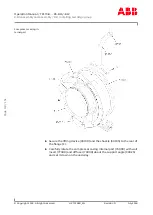
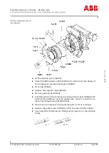
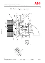
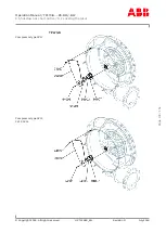
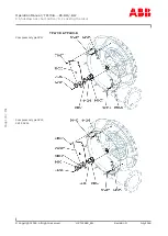
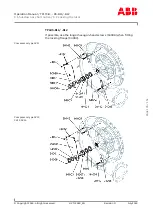
Fit locking device (90020) in accordance with following illustrations.
Make sure the intermediate rings, the spacer ring and the adapter ring
are fitted correctly.
All parts must be kept clean and free from grease.
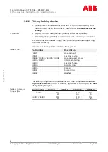
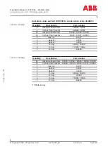
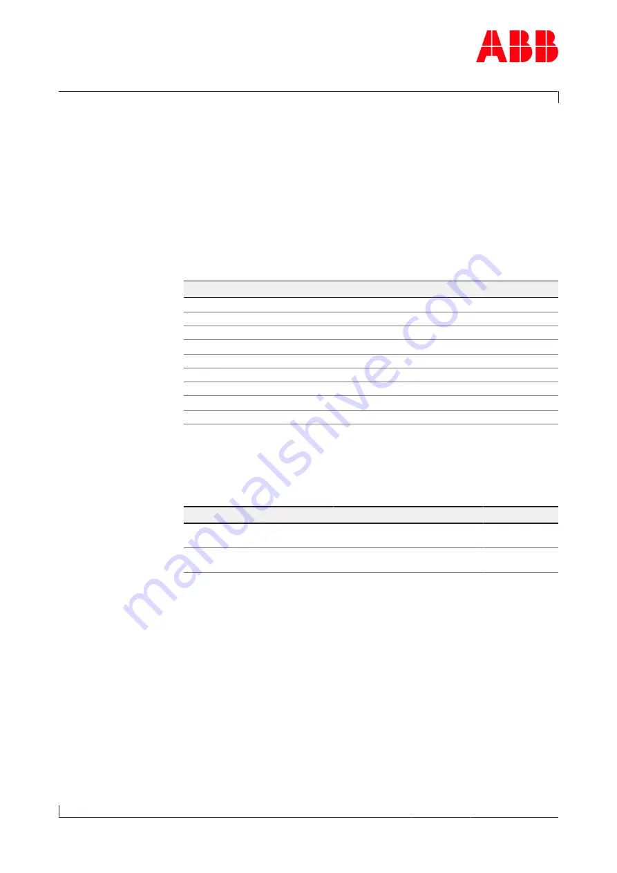
Table of tools
Part number
Description
74027
Hexagon nut
90020
Locking device
90442 / 94006 / 94007 / 94008
Hexagon-head screw
94001 / 94002
Intermediate ring
94003
Locking flange
94004
Adapter ring
94005
Clamp
94031
Spacer ring
94032
Washer
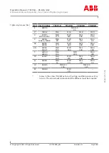
The locking flange (94003) must be fitted to the compressor wheel
us-
ing at least 9 screws
(94007 or 94008), tightened according to the
Table
of tightening torques
.
Table of tightening
torques [Nm]
Part number
TPL73-B
TPL77-B
TPL80-B
TPL85-B
94006
M8
25
M10
45
M12
75
94007 / 94008
M8
15
M10
35
M12
60
Page
132
/
151

