Turbocharger VTR..4
Seite / Page 47
Demontage und Montage
Kap. / Chap. 5
Disassembly and assembly
ABB Turbo Systems Ltd
10020
- M -
6 Düsenring ersetzen
- Lager ausbauen (s. Abschn. 4.1 und 4.2).
- Rotor ausbauen (s. Absch. 5.1).
Vorsicht !
Beschädigten Düsenring nur von autori-
sierten Service-Stellen der ABB Turbo
Systems AG wechseln lassen.
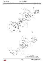
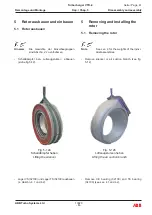
- Kühlwasserleitungen und Abgasleitung vom Gas-
eintrittsgehäuse (50000) trennen.
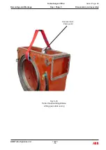
- Seil um Gaseintrittsgehäuse (50000) schlingen
und am Hebezeug einhängen.
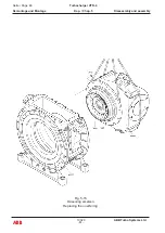
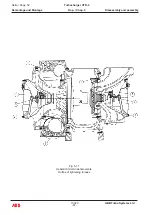
- Muttern (61010) lösen und entfernen.
- Gaseintrittsgehäuse (50000) ev. mit leichten
Hammerschlägen (nur Blei- oder Kupferhammer
verwenden) vom Gasaustrittsgehäuse (60000)
lösen und entfernen.
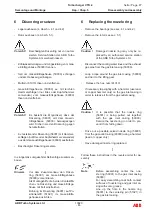
Vorsicht !
Es besteht die Möglichkeit, dass der
Düsenring (56001) mit dem Gasein-
trittsgehäuse (50000) herausgezogen
wird. Sichern sie den Düsenring gegen
herunterfallen.
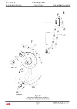
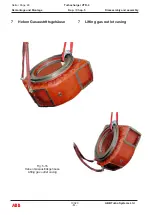
- Ev. festsitzender Düsenring (56001) mit Hammer-
schlägen (nur Blei- oder Kupferhammer verwenden)
aus dem Gasaustrittsgehäuse (60000) austreiben.
- Beschädigter Düsenring ersetzen.
In sinngemäss umgekehrter Reihenfolge zusammen-
bauen.
Hinweis
Vor dem Zusammenbau den Düsen-
ring (56001) am Gaseintrittsgehäuse
(50000) vorzentrieren.
Als Montagehilfe die beiden Kontaktflä-
chen von Düsenring und Gaseintrittsge-
häuse mit Fett einstreichen.
Bohrung im Düsenring (56001) auf Po-
sitionierstift (51021) im Gaseintritts-
gehäuse ausrichten.
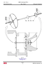
6 Replacing the nozzle ring
- Remove the bearings (see sec. 4.1 and 4.2)
- Remove the rotor (see sec. 5.1)
Caution !
Damaged nozzle ring may only be re-
placed by an authorized service station
of the ABB Turbo Systems Ltd.
- Disconnect the cooling water lines and the exhaust
gas pipe from the gasinlet casing (50000).
- Loop a rope around the gas inlet casing (50000)
and tie it to the lifting gear.
- Relaese the hex. nuts (61010)
- If necessary tap slightly with a hammer (use lead-
or copper hammer only) on the gas inlet casing in
order to release it from the gas outlet casing.
Caution !
It is possible that the nozzle ring
(56001) is being pulled out together
with the gas inlet casing (50000).
Secure the nozzle ring in order to pre-
vent it from falling down.
- Drive out a possible seized nozzle ring (56001)
from the gas outlet casing (60000) using a hammer
(lead or copper only).
- Have damaged nozzle ring replaced.
Follow these instructions in the reverse order for as-
sembly
.
Note
Before assembling center the noz-
zle ring (56001) to the gas inlet casing
(50000).
For easy assembling coat both contact
surfaces of nozzle ring and gas inlet ca-
sing with some grease.
Line up the hole in the nozzle ring
(56001) to the centering pin (51021) in
the gas inlet casing.
Summary of Contents for HT846493
Page 4: ......
Page 5: ...0 Preliminary remarks Vorbemerkungen ...
Page 6: ......
Page 18: ......
Page 19: ...1 Instructions on safety and hazards Sicherheits und Gefahrenhinweise ...
Page 20: ......
Page 34: ......
Page 35: ...2 Putting into operation Inbetriebnehmen ...
Page 36: ......
Page 53: ...3 Operation and maintenance Betrieb und Unterhalt ...
Page 54: ......
Page 99: ...Troubleshooting Beheben von Störungen 4 ...
Page 100: ......
Page 107: ...Disassembly and assembly Demontage und Montage 5 ...
Page 108: ......
Page 162: ......
Page 163: ...Taking out of operation Ausserbetriebnehmen 6 ...
Page 164: ......
Page 180: ......
Page 181: ...Appendix Anhang 7 ...
Page 182: ......
Page 184: ... 10021 ABB Turbo Systems Ltd E Seite Page 2 ABB Turbocharger VTR 4 Anhang Kap Chap 7 Appendix ...
Page 228: ......
Page 229: ...Approved lubricating oils Zugelassene Schmieröle 8 1 ...
Page 230: ......
Page 235: ...ABB Switzerland Ltd Turbocharging Bruggerstrasse 71a CH 5401 Baden Switzerland ...

