ProcessMaster FEP610, HygienicMaster FEH610
| OI/FEP610/FEH610-EN Rev. B 9
2.2
Model variants
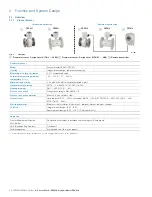
Integral mount design
For devices with an integral mount design, the transmitter and
the flowmeter sensor form a single mechanical unit
Remote mount design
For devices with a remote mount design, the transmitter and
flowmeter sensor are mounted in separate locations.
The electrical connection between the transmitter and the
flowmeter sensor is provided by a signal cable.
When the minimum conductivity of the measuring medium is
20 μS/cm, a maximum signal cable length of 50 m (164 ft) is
possible.
Notes on ProcessMaster
The ProcessMaster flowmeter sensor is available in two
models, which are distinguished by the design level (A / B).
2.3
Measuring principle
Measurements performed by the electromagnetic flowmeter
are based on Faraday’s law of induction. A voltage is
generated in a conductor when it moves through a magnetic
field.
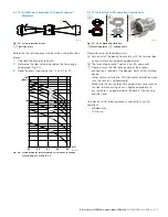
Fig. 3:
Electromagnetic flowmeter schematic
1
Magnet coil
2
Measuring tube in electrode plane
3
Signal
electrode
v
D
B
U
~
1
v
D
qv
4
2
qv
U ~
1
U
1
Signal voltage
B Magnetic
induction
D Electrode
spacing
v Average
flow
velocity
q
v
Volume flow
This principle is applied to a conductive fluid in the measuring
tube through which a magnetic field is generated
perpendicular to the flow direction (see Fig. 3).
The voltage induced in the fluid is measured by two electrodes
located diametrically opposite each other. This signal voltage
is proportional to the magnetic induction, the electrode
spacing and the average flow velocity.
Considering that the magnetic induction and the electrode
spacing are constant values, a proportionality exists between
the signal voltage UE and the average flow velocity.
From the equation for calculating the volume flowrate, it
follows that the signal voltage is linearly proportional to the
volume flowrate.
The induced voltage is converted by the transmitter to
standardized, analog and digital signals.
G12000
U₁
y
z
x
v
B
D
E
1
2
2


