background image


15

ABB i-bus

®

 EIB / KNX

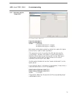
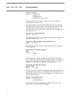
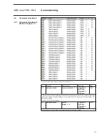
Fig. 10: Communication objects Analogue Actuator AA/S 4.1

No.

Function

Object name

Data type

Flags

0-3

Analogue output

Input value output  1…4

1 Byte EIS 6
DPT 5.001

2 Byte EIS 5
DPT 9.0xx

C, W

1-byte or 2-byte objects with which the value of the output can be set. In 1-byte mode a new 
input value can be assumed rapidly or it is possible to dim to the value. The input object can 
be time monitored. 

(see also object “Alarm Output …”)

4-7

Analogue output

Status 
Output  1…4

1 Byte EIS 6
DPT 5.001

2 Byte EIS 5
DPT 9.0xx

C, R, T

1-byte object or 2-byte object for displaying the current output value.

4.3 Communication 

object

4.3.1  

Communication objects
AA/S 4.1, Output 1 – 4

Commissioning

Summary of Contents for i-bus EIB/KNX AA/S 4.1

Page 1: ...Product Manual ABB i bus EIB KNX Analogue Actuator AA S 4 1 Analogue Actuator Module AAM S 4 1 Intelligent Installation Systems ...

Page 2: ...f 1 2 Subject to changes and errors excepted Exclusion of liability Despite checking that the contents of this document match the hardware and software deviations cannot be completely excluded We therefore cannot accept any liability for this Any necessary corrections will be inserted in new versions of the manual Please inform us of any suggested improvements ...

Page 3: ... Parameter window 10 4 2 1 Parameter window General Parameters 10 4 2 2 Parameter window Output X 1 2 11 4 2 3 Parameter window Output X 2 2 13 4 3 Communication object 15 4 3 1 Communication objects AA S 4 1 Output 1 4 15 4 3 2 Communications objects AAM S 4 1 Output 5 8 17 5 Planning and application 19 5 1 Status displays 19 5 1 1 Analogue Actuator AA S 4 1 19 5 1 2 Analogue Actuator Module AAM ...

Page 4: ...rised to a previously set format Outputs which are not required can be switched off The output signals can be forced controlled The number of analogue outputs can be increased to 8 using the Analogue Actuator Module AAM S When combined with the Dimming switch sensor function the Analogue Actuator and the Analogue Actuator Module can be used as an active control unit for dimming applications Note T...

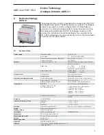
Page 5: ...load Voltage signal 욷 1 kΩ Current signal 울 500 Ω Output current Voltage signal Max 10 mA per channel Current signal Max 20 mA per channel Operating and display elements Device status display Status LED 3 colour red orange green Output signal A1 A4 display Status LED yellow Programming button and LED red For assignment of the physical address Connections EIB KNX Bus connection terminal black red A...

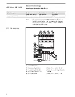
Page 6: ...ircuit diagram AA S 4 1 1 2 3 4 Bus connecting terminal Programming LED button Status LED output A1 A4 Status LED device 5 6 7 Connection terminals A1 A4 Connection for Analogue Actuator Module Connection terminal 24 V AC 2 1 1 Circuit diagram Device Technology Analogue Actuator AA S 4 1 Application program Number communication objects Max number of group addresses Max number of associations Analo...

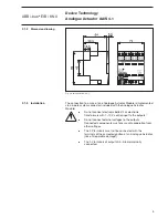
Page 7: ...rmers with 1 10 V control input to the outputs 쐌 Do not connect external voltages to the outputs Connected components must ensure safe separation from other voltages 쐌 The 0 V terminals must not be connected with the terminals of the same designation of an Analogue Actuator risk of irreparable damage 쐌 The 0 V terminals of outputs A5 A8 are internally connected 2 1 2 Dimension drawing 2 1 3 Instal...

Page 8: ...puts A5 A8 Signal type 0 1 V DC 0 20 mA 0 10 V DC 4 20 mA depending on parameterisation Output signal load Voltage signal 욷 1 kΩ Current signal 울 500 Ω Output current Voltage signal Max 10 mA per channel Current signal Max 20 mA per channel Operating and display elements Device status display Status LED red Output signal A5 A8 display Status LED yellow Connections Analogue outputs A5 A8 24 V AC po...

Page 9: ...t diagram AAM S 4 1 1 Connection to analogue actuator 4 Connection terminals A5 A8 2 Status LED output A5 A8 5 Connection terminal 24 V AC 3 Status LED device 3 1 1 Circuit diagram Device Technology Analogue Actuator Module AAM S 4 1 ...

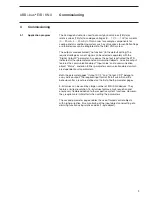
Page 10: ...them to their original state Removal or addition of modules without adapting the project and subsequent downloading into the Analogue Actuator is not permitted as this will result in system malfunctions 쐌 Do not connect electronic ballast s or electronic transformers with 1 10 V control input to the outputs 쐌 Do not connect external voltages to the outputs Connected components must ensure safe sep...

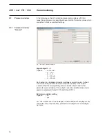
Page 11: ...Input value and a communication object Status and even further parameter communication objects which are dependent on its parameters Both the parameter pages Output X 1 2 and Output X 2 2 belong to every active output The required input format 16 bit or 8 bit and the behaviour after a reset are defined on the first of both parameter pages 8 bit values can be used by a large number of EIB KNX devic...

Page 12: ...ltage or current source Outputs which are not required can be deactivated no function If the output is deactivated the corresponding communication objects and further parameters remain hidden If the output is used two additional parameter pages are displayed Output X 1 2 and Output X 2 2 Extension module existing Options no yes Yes The outputs 5 8 of the Analogue Actuator Module are displayed They...

Page 13: ... is set the parameter Time between 2 of 255 dimming steps and Response on reception of value is displayed on the Output X 2 2 parameter window see 4 2 3 Input value for 0 output value Input value for 100 output value Options 32768 32767 0 or 1000 For setting the input value range for 0 or 100 output value with 16 bit input format If the 8 bit mode has been selected with the Input format parameter ...

Page 14: ...s voltage failure Response to bus voltage failure Options last value output value in If the supply voltage is present the output can either retain the last value or set the output to a new value with a bus voltage failure Output value in If this option is selected the parameter Output value in is displayed Output value in Options 0 100 0 For setting the output value in with bus voltage failure Res...

Page 15: ...his parameter will determine at which object value forced control is active If the forced control object is deactivated the output will assume the value in accordance with the Input value object If both forced control objects are active forced control object 1 has the higher priority Forced control active at 1 or 0 telegram The parameters Output value in case of forced control 1 or 2 in are displa...

Page 16: ...s 0 100 0 The output assumes the value parameterised here when the monitoring time is exceeded Time between 2 of 255 dimming steps Basis Options 10 ms 100 ms 1 s With this parameter the basis for the dimming speed which the output uses is determined in 8 bit mode if it is controlled via the 4 bit object or if the parameter Response on reception of value is set to the dimming approach and the outpu...

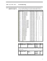
Page 17: ...h the value of the output can be set In 1 byte mode a new input value can be assumed rapidly or it is possible to dim to the value The input object can be time monitored see also object Alarm Output 4 7 Analogue output Status Output 1 4 1 Byte EIS 6 DPT 5 001 2 Byte EIS 5 DPT 9 0xx C R T 1 byte object or 2 byte object for displaying the current output value 4 3 Communication object 4 3 1 Communica...

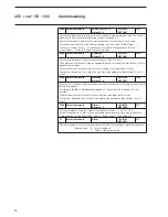
Page 18: ... only available in 8 bit mode The switch object is not monitored if cyclic monitoring of the input value is active The objects Switching of an output is only visible if the parameter Input format is set to 8 Bit 20 23 Analogue output Dimming Output 1 4 4 Bit EIS 2 DPT 3 007 C W 4 bit object to increase or decrease the output value continuously with a dim switch The dim speed is adjustable Accordin...

Page 19: ...5 8 1 Byte EIS 6 DPT 5 001 2 Byte EIS 5 DPT 9 0xx C W 1 byte or 2 byte objects with which the value of the output can be set In 1 byte mode a new input value can be assumed rapidly or it is possible to dim to the value The input object can be time monitored see also object Alarm Output 33 36 Extension module Status Output 5 8 1 Byte EIS 6 DPT 5 001 2 Byte EIS 5 DPT 9 0xx C R T 1 byte object or 2 b...

Page 20: ...he input value is active The objects Switching of an output is only visible if the parameter Input format is set to 8 Bit 49 52 Extension module Dimming Output 5 8 4 Bit EIS 2 DPT 3 007 C W 4 bit object to increase or decrease the output value continuously with a dim switch The dim speed is adjustable According to the EIB KNX standard dimming on is possible and dimming off is not possible The dim ...

Page 21: ...y when the 24 V AC power supply and EIB KNX bus voltage are present Status LED device 3 colour red orange green Status Off No voltage supply On Module scan via Analogue Actuator flashes quickly2 Scan Analogue Actuator flashes slowly1 Undervoltage on module connection short circuit Us flashes quickly2 No project parameterisation fault flashes slowly1 Module scan completed engineering OK address ass...

Page 22: ...odule is initialised and put into operation Precondition The LED must have switched off beforehand LED display in normal operation On Module is not ready for operation fault Off Module is initialised and programmed Precondition The LED must have switched off beforehand 1 Flashes slowly 1 s 2 Flashes quickly 2 s Status LED Output A5 A8 yellow Status On Output signal is higher than zero Off Output s...

Page 23: ... that they cover the required value range as well as possible with the common parameter Factor of input value In order to obtain the highest possible internal resolution a small factor should be selected Examples The following parameters are recommended in order to receive a direct implementation of the input value in volts with an output signal of 0 10 V Input value for 0 0 Input value for 100 10...

Page 24: ...forced control object 쐌 If the output receives a new incoming telegram but does not execute it because a forced control is active Example The output is set to 9 volts due to a forced control The Input value object receives the value 5 volts The value is not set due to the forced control The status object reports back with the 9 volts value The new input value of 5 volts is stored internally and se...

Page 25: ...t type 3 007 via the 4 bit object The dimming speed depends on both parameters Time between 2 of 255 dimming steps Basis and Time between 2 of 255 dimming steps Factor The preset value for the range from 0 to 100 is about 5 seconds The shortest time is about 2 5 seconds The longest time is about 65 000 seconds which is 1083 minutes or about 18 hours Depending on the parameter Response on reception...

Page 26: ...to not available Accordingly the ETS does not show these communication objects Forced control can be active if the object features either the value 1 or the value 0 For the active state a fixed value is set with the parameter Output value in case of forced control If the Forced control object is inactive the output automatically assumes the value which corresponds with the Input value object If bo...

Page 27: ... communication objects Input value and Forced control in conjunction with monitoring The arrows indi cate the times for the telegrams With inactive forced control the object Input value defines the state of the output If Forced control 2 becomes active the output assumes the parameterised value here 70 Telegrams to the object Input value are not carried out However the value is stored internally F...

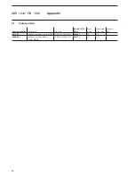
Page 28: ...r No bbn 40 16779 EAN Price group Unit weight 1 pc kg Pack unit Pcs AA S 4 1 Analogue Actuator 4 fold MDRC 2CDG 120 005 R0011 65886 7 20 0 2 1 AAM S 4 1 Analogue Actuator Module 4 fold MDRC 2CDG 120 006 R0011 65887 4 20 0 15 1 Appendix A 1 Ordering details ...

Page 29: ...The information in this leaflet is subject to change without further notice Pub No 2CDC 505 064 D0201 Your EIB KNX Partner ...

Reviews: