5
ABB i-bus
®
EIB / KNX
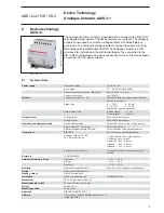
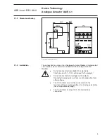
Fig. 3: Analogaktor AA/S 4.1
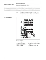
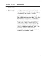
The connection to a max. of one Analogue Actuator Module is implemented
via a 6-pole system connector (included with the Analogue Actuator
Module).
쐌
Do not connect electronic ballast’s or electronic
transformers with 1 – 10 V control input to the outputs!
쐌
Do not connect external voltages to the outputs.
Connected components must ensure safe separation from
other voltages.
쐌
The 0 V terminals must not be connected with the
terminals of the same designation of an Analogue Actuator
(risk of irreparable damage!).
쐌
The 0 V terminals of outputs A5...A8 are internally
connected.
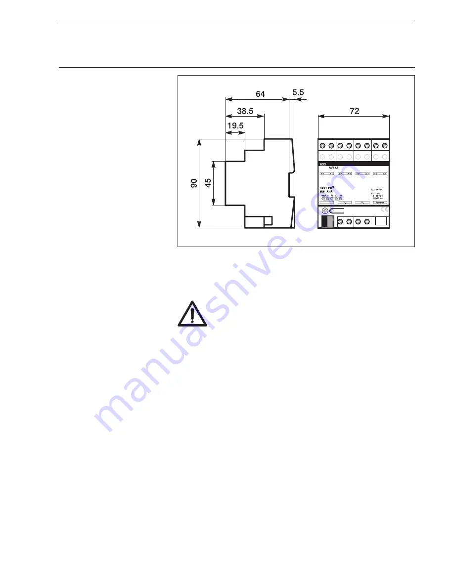
2.1.2 Dimension
drawing
2.1.3 Installation
Device Technology
Analogue Actuator AA/S 4.1


