ABB i-bus
®
KNX
Function
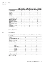
FCC/S 1.X.X.1 | 2CDC 508 200 D0211 Rev A 79
FCC/S
1.1.1.1
FCC/S
1.1.2.1
FCC/S
1.2.1.1
FCC/S
1.2.2.1
FCC/S
1.3.1.1
FCC/S
1.3.2.1
FCC/S
1.4.1.1
FCC/S
1.5.1.1
FCC/S
1.5.2.1
Temperature sensor
(e.g. room temperature)
4
4
4
4
4
4
4
4
4
Fan output
1
1
1
1
1
1
1
1
1
3-speed fan
1
1
1
1
–
–
1
–
–
2-speed fan
1
1
1
1
–
–
1
–
–
1-speed fan
1
1
1
1
–
–
1
–
–
Continuous fan (0 … 10 V)
–
–
–
–
1
1
–
1
1
16 A outputs (resistive load)
1
1
1
1
1
1
1
1
1
Electrical auxiliary heater
1
1
1
1
1
1
1
1
1
Electronic valve outputs
2
2
–
–
–
–
1
2
2
Electrothermal Valve Drives
(PWM)
2
2
–
–
–
–
1
2
2
Motor-Driven Valve Drives
(3-point)
1
1
–
–
–
–
–
1
1
Analog outputs (0 … 10 V)
–
–
2
2
2
2
–
–
–
Analog Valve Drives
–
–
2
2
2
2
–
–
–
Table 22: Functional overview
For more information see: .
4.3
Input functions
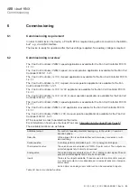
The following table provides an overview of the functions possible with the inputs of the FCC/S and
the application:
Function
a
b
c
d
Connection of analog room control
unit
X
Binary signal input (floating)
X
X
X
X
Temperature sensor
PT100
X
X
X
X
PT1000
X
X
X
X
KT/KTY
X
X
X
X
KT/KTY user de-
fined
X
X
X
X
NTC10k
X
X
X
X
NTC20k
X
X
X
X
NI‑1000
X
X
X
X
Dew point sensor (floating)
X
X
X
X
Filling level sensor (floating)
X
X
X
X
Window contact (floating)
X
X
X
X
Table 23: Input functions


