ABB i-bus
®
KNX
Mounting and installation
FCC/S 1.X.X.1 | 2CDC 508 200 D0211 Rev A 83
5
Mounting and installation
5.1
Information about mounting
The installation position can be selected as required.
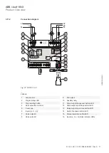
The electrical connection is implemented using screw terminals. The connection to the bus is im-
plemented using the supplied bus connection terminal. The terminal assignment is located on the
housing.
The device is ready for operation after connection to the bus voltage.
Note
The maximum permissible current of a KNX line must not be exceeded.
During planning and installation ensure that the KNX line is correctly dimensioned.
The device has a maximum current consumption of 12 mA.
DANGER - Severe injuries due to touch voltage
Feedback from differing phase conductors can produce touch voltages and lead to severe in-
juries.
Operate the device only in a closed housing (distribution board).
Disconnect all phases before working on the electrical connection.
5.2
Mounting on DIN rail
The device is held and removed exclusively without auxiliary tools.
Make sure the device is accessible for operation, testing, visual inspection, maintenance and re-
pair.
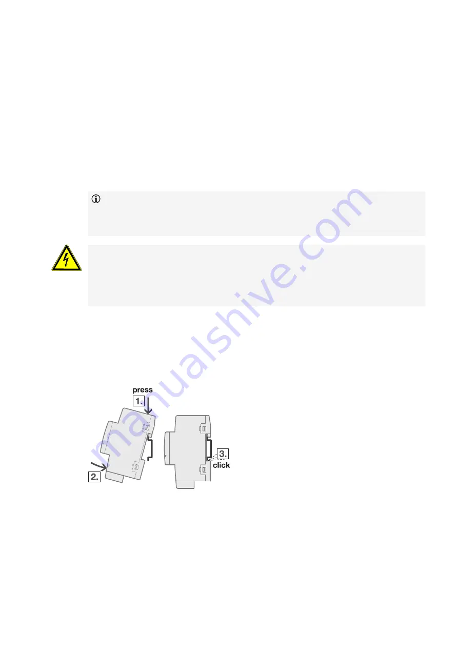
Fig. 28: Mounting on DIN rail
2CDC072013F0015
1. Place the DIN rail holder on the upper edge of the DIN rail and push down.
2. Push the lower part of the device toward the DIN rail until the DIN rail holder engages.
ð
The device has now been mounted on the DIN rail.
3. Relieve the pressure on the top of the housing.


