background image

ABB i-bus

£

 KNX 

Commissioning 

© 2010 ABB STOTZ-KONTAKT GmbH 


52 

3.2.4.3

Parameter window 
Direct operation

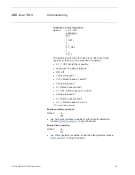
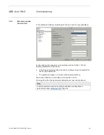
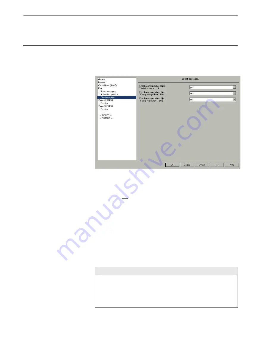
This parameter window is visible if in parameter window 

Fan

 the option 

yes

has been selected in the 

Enable direct operatio

n parameter. 

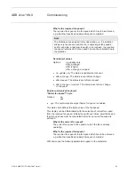
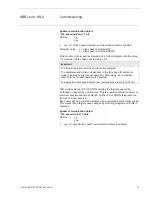
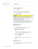
Enable communication objects 
“Switch speed x” 1 bit 

Options: no 
 yes

x

yes:

 Three 1 bit communication objects 

Speed 1

,

Speed 2

 and 

Speed 3

are enabled. 

The Fan Coil Actuator receives a setting telegram via these communication 
objects.  

Telegram value 

1 = fan speed x is switched on 
0 = fan speed x is switched off 

If several ON/OFF telegrams are received consecutively in a short period of 
time at various 

Fan speed 1-3

 communication objects, the value last 

received by the fan control is the decisive value. 
An OFF telegram to one of the three communication objects 

Fan speed 1-3

,

switches off the fan completely. 

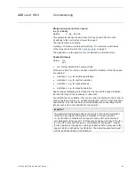
Important 

The forced operation remains valid and is considered.  

The parameterised minimum dwell time in the fan speed for automatic 
mode is ignored during manual operation. Accordingly, an immediate 
reaction to the manual operation is detected. 

The delay time with speed switch over remains active to protect the fan. 

Summary of Contents for i-bus KNX FCA/S 1.1M

Page 1: ...ABB i bus KNX Fan Coil Actuator FCA S 1 1M Product Manual ...

Page 2: ......

Page 3: ... 2 Control value 2 pipe 31 3 2 3 4 HVAC System 2 Control value 2 pipe with switching object 32 3 2 3 5 HVAC system 2 Control value 4 pipe 34 3 2 4 Parameter window Multi level fan 35 3 2 4 1 Parameter window Status messages 41 3 2 4 2 Parameter window Automatic operation 46 3 2 4 3 Parameter window Direct operation 52 3 2 5 Parameter window Two level fan 54 3 2 6 Parameter window One level fan 55 ...

Page 4: ...onnection 123 4 1 2 2 Fan with speed switching 123 4 1 3 Configuration of a HVAC system with Fan Coil units 124 4 1 4 Design of a Fan Coil unit 124 4 1 5 Pipe systems 125 4 1 5 1 2 pipe system configuration 126 4 1 5 2 2 pipe system HEATING and COOLING 127 4 1 5 3 2 pipe system HEATING or COOLING 128 4 1 5 4 3 pipe system configuration 129 4 1 5 5 4 pipe system configuration 130 4 2 System configu...

Page 5: ... KONTAKT GmbH iii 4 5 1 Valve HEATING COOLING 153 4 6 Fast heat up cool down 154 4 6 1 Heat up 154 4 6 2 Cooling down 155 A Appendix 157 A 1 Scope of delivery 157 A 2 Status byte forced operation 158 A 3 Ordering information 159 Notes 160 ...

Page 6: ......

Page 7: ...ating and cooling valves Multi level fans with up to three fan speeds can be switched via floating contacts Furthermore two binary inputs e g for monitoring of a window contact and the dew point are available The additional contact is used for example to control an electric heater 1 1 Use of the product manual This manual provides you with detailed technical information relating to the Fan Coil Ac...

Page 8: ...ming examples Important These safety instructions are used as soon as there is danger of a malfunction without risk of damage or injury Caution These safety instructions are used if there is a danger of damage with inappropriate use Danger These safety instructions are used if there is a danger for life and limb with inappropriate use Danger These safety instructions are used if there is a danger ...

Page 9: ... for window contact and dew point monitoring The scanning voltage for the binary inputs is provided by the device The actuator is a modular installation device with a module width of 4 space units in ProM Design for installation in the distribution board The connection to the ABB i bus is established using the front side bus connection terminal The Fan Coil Actuator does not require an auxiliary v...

Page 10: ... S 1 1M Outputs Switching contact 16 A 10 AX 1 Switching contact 6 A 3 Electronic 0 5 A 4 1 2 2 Functional overview FCA S 1 1M Inputs 2 Window contact 1 Drip tray 1 FCA S 1 1M Outputs 16 A 10 AX switch 1 Electrical auxiliary heater 1 Outputs 6 A switches 3 3 speed fan 3 Outputs 0 5 A switches 4 Valve HEATING 2 Valve COOLING 2 ...

Page 11: ...ay 6 A Electronic outputs 0 5 A 0 25 W 1 0 W 0 6 W 1 0 W Connections KNX Via bus connection terminals Inputs Outputs Via screw terminals Operating and display elements Programming button LED For assignment of the physical address Button LED For toggling between manual operation operation via ABB i bus and displays Button ON OFF LED Programmable function Fan speed button For switching through the i...

Page 12: ...n as required Weight 0 1 kg Housing colour Plastic housing grey Approvals KNX to EN 50 090 1 2 Certification CE mark in accordance with the EMC guideline and low voltage guideline 2 1 1 Electronic outputs Rated values Number 4 non isolated short circuit proofed Un rated voltage 24 230 V AC 50 60 Hz In rated current per output pair 0 5 A Continuous current 0 5 A resistive load at TA up to 20 C 0 3 ...

Page 13: ...ay not be exceeded What do the terms AC1 AC3 and AC5a mean In Intelligent Installation Systems different switching capacity and performance specifications which are dependent on the special application have become established in industrial and residential systems These performance specifications are rooted in the respective national and international standards The tests are defined so that typical...

Page 14: ...C1 AC3 and AC5a mean In Intelligent Installation Systems different switching capacity and performance specifications which are dependent on the special application have become established in industrial and residential systems These performance specifications are rooted in the respective national and international standards The tests are defined so that typical applications e g motor loads industri...

Page 15: ... x 18 SF 23 24 W ABB EVG T5 1 x 24 CY 23 36 W ABB EVG 1 x 36 CF 14 58 W ABB EVG 1 x 58 CF 11 80 W Helvar EL 1 x 80 SC 10 1 For multiple element lamps or other types the number of electronic ballasts must be determined using the peak inrush current of the electronic ballasts Application program Maximum number of communication objects Maximum number of group addresses Maximum number of associations ...

Page 16: ...tion 5 Button 6 LED 7 Binary inputs A B 8 Button fan speed 9 LED fan speed 1 3 10 Button switching contact 11 LED switching contact 12 Button ON OFF 13 LED ON OFF 14 Output switching contact 15 Fan 16 Valve HEATING 17 Valve COOLING 18 LED valve HEATING 19 Button valve HEATING 20 LED valve COOLING 21 Button valve COOLING 22 LED binary input A 23 Button binary input A 24 LED binary input B 25 Button...

Page 17: ...ioning requirements In order to commission the device a PC with ETS from ETS2 V1 3a or higher as well as an interface to the ABB i bus e g via a KNX interface is required The device is ready for operation after connection to the bus voltage No additional auxiliary voltage is required The installation and commissioning may only be carried out by qualified electrical specialists The appropriate norm...

Page 18: ...es before it appears due to the complexity of the device Assignment of the physical address The assignment and programming of the physical address is carried out in the ETS Cleaning If devices become dirty they can be cleaned using a dry cloth Should a dry cloth not remove the dirt the device can be cleaned using a slightly damp cloth and soap solution Corrosive agents or solutions should never be...

Page 19: ...hese are used for example to monitor the window contact and condensation dew point The 6 A outputs are available for Fan Coil applications Caution Improper switching will cause destruction of the fan motors The technical data of the fan must be observed e g speed or switching function For further information see Parameter window Fan multi level page 35 The Fan Coil Actuator features relays in each...

Page 20: ...oom through a grill Air supply Fan Coil units are available as recirculation or a mixed air devices x Recirculation devices The room air is directed past heat exchangers by the fans x Mixed air devices The room air is mixed with fresh air The mixing ratio between re circulated and fresh air can usually be adjusted 3 2 Parameters The parameterisation of the Fan Coil Actuator is implemented using th...

Page 21: ...correspond to the parameterisation or the communication object values If communication objects are read during the sending and switching delay e g by a visualisation system these read requests are stored and a response is sent after the send and switching delay has been completed An initialisation time of about two seconds is included in the delay time The initialisation time is the time that the ...

Page 22: ... communication object is sent after the set sending and switching delay x yes Additional parameters appear Telegram repeated in s 1 65 535 Options 1 60 65 535 Here the time interval at which the In operation communication object cyclically sends a telegram is set Send value cyclically Options 0 1 The setting defines the value that the communication object sends on the bus Enable input A binary inp...

Page 23: ... yes x yes A 1 bit communication object Request status values is enabled Via this communication object all status messages can be requested provided that they have been parameterised with the option after a change or request With option yes the following parameters are visible Recall with object value Options 0 1 0 or 1 x 0 The status messages are sent with the value 0 x 1 The status messages are ...

Page 24: ... operations and programmed dwell times are not considered If manual operation is deactivated the fan sets to a speed to which it would also be set without manual operation e g via the value of the communication objects The setting occurs with the parameterised dwell times Switch on of manual operation Press button until the yellow LED lights continuously Switch off of manual operation Press button...

Page 25: ...how long the Fan Coil Actuator remains in the Manual operation mode after pressing the button x no The Fan Coil Actuator remains in Manual operation until the button is pressed again x after X minutes The Fan Coil Actuator remains in Manual operation after the last button push until either button is pushed again or the programmed time has timed out Enable communication object Status man operation ...

Page 26: ...functions with both options x Indication Status automatic The LED indicates the current operating state of the Fan Coil Actuator LED on fan automatic activated LED off fan automatic not activated x LED button with objects The communication objects LED ON OFF No 3 and Button ON OFF No 2 appear With these communication objects it is possible to freely select the function Speed Options enabled disabl...

Page 27: ...get position is approached that would have been set without manual operation With manual operation a set characteristic curve correction is not taken into consideration Button function at overload The description concerns the button HEATING and the LED HEATING The device is in the KNX operating state and the output of the HEATING valve has a malfunction e g due to an overload The valve HEATING LED...

Page 28: ...es of the input and the LED are changed x Push buttons Press button input closed LED on Release button input opened LED off Note By pressing button binary input A is simulated The display indicates the current input state The parameterised features are executed Input B The operation of input A does not differ from the operation of input B Output Options enabled disabled With this parameter the but...

Page 29: ...witching object 2 Control values 4 pipe This parameter defines the pipe system which is used with the Fan Coil Actuator The individual functions are described in the following chapters Important If a valve is deactivated due to a conversion of the HVAC system the valve will be fully closed A correction curve which may be set will be ignored Monitoring control values e g thermostat Options no yes x...

Page 30: ...NG COOLING If a setting variable is not received within the parameterised time a communication malfunction has occurred and emergency operation is activated Important It must be assured that the monitoring time is set to at least factor 3 larger than the set sending time of the thermostat The reaction of the FCA S to a setting value not received can be defined in the following parameters Send obje...

Page 31: ... is not monitored in the process Valve HEATING Via communication object Control value HEATING COOLING the valve HEATING and the fan are controlled For further information see Configuration of a HVAC system with Fan Coil units page 124 Operation HEAT COOL after bus voltage recovery Options unchanged HEATING COOLING Using this parameter the reaction after bus voltage recovery is set x unchanged Afte...

Page 32: ...For further information see Design of a HVAC system with Fan Coil Units page 124 Operation HEAT COOL after bus voltage recovery Options unchanged HEATING COOLING Using this parameter the reaction after bus voltage recovery is set x unchanged After bus voltage recovery the state which existed before bus voltage failure is set x HEATING After bus voltage recovery the HEATING state is set x COOLING A...

Page 33: ... a value 0 is received this is ignored if the other control value 0 Caution With a 2 pipe HVAC system both the Control value HEATING as well as the Control value COOLING act on the heating valve electronic outputs O P Please note that always the last control value received controls the heating valve For 2 pipe systems only the communication objects for the HEATING valve are relevant The communicat...

Page 34: ...ING act on the HEATING valve electronic outputs O P Please note that always the last control value received and the switching object control the HEATING valve For 2 pipe systems only the communication objects for the HEATING valve are relevant The communication objects in conjunction with the COOLING valve e g status forced operation or valve purge are not effective For further information see Des...

Page 35: ...OOLING Options 1 0 With this parameter you set the object value used to toggle between HEATING and COOLING x 1 As soon as a telegram with the value 1 is received HEATING is activated and COOLING is deactivated x 0 As soon as a telegram with the value 0 is received HEATING is activated and COOLING is deactivated ...

Page 36: ... a HVAC system with Fan Coil Units page 124 Operation HEAT COOL after bus voltage recovery Options unchanged HEATING COOLING Using this parameter the reaction after bus voltage recovery is set x unchanged After bus voltage recovery the state which existed before bus voltage failure is set x HEATING After bus voltage recovery the HEATING state is set x COOLING After bus voltage recovery the COOLING...

Page 37: ... fan with one speed should be controlled Speed on 2 limit Option no yes The fan speeds can be limited to two here The following settings are the same as those for a three speed fan but are only limited to two speeds x no A three speed fan is controlled x yes A two speed fan is controlled via fan speeds 1 and 2 Fan speed 3 is non functional Fan operation Mode See techn data of the fan Option Change...

Page 38: ...rameterised delay time between two fan speeds has the effect that the current fan speed must be switched on for at least this time before the next valve speed is switched on The parameterised minimum dwell time in a fan speed has the same effect as a changeover switch i e it is only active in automatic mode and is added to the switchover delay x Changeover switch The following parameter appears De...

Page 39: ...ed operation for example a recirculation valve OFF and fan ON can be implemented x yes A 1 bit Forced operation communication object is enabled Further parameters appear at the same time Forced operation on object value Options 1 0 x 1 Forced operation is activated by a telegram with value 1 x 0 Forced operation is activated by a telegram with value 0 Note During forced operation the settings set ...

Page 40: ...mited to speed 1 x 1 OFF limited to speed 1 and off x 2 limited to speed 2 x 2 1 limited to speed 2 and 1 x 2 1 OFF limited to speed 2 1 and off x 3 limited to speed 3 x 3 2 limited to speed 3 and 2 x 3 2 1 limited to speed 3 2 and 1 The control value is ignored Enable automatic operation Options no yes x yes Automatic operation is enabled Furthermore the parameter window Automatic operation on pa...

Page 41: ...eed is directly switched on The delay between the switchover of two fan speeds contact change is considered The dwell times in a fan speed which are considered in automatic mode are inactive and will only be considered after the start up phase The start up behaviour is a technical characteristic of the fan For this reason this behaviour has a higher priority than an active limitation or forced ope...

Page 42: ...the parameter window Automatic operation is only active and programmable if the option yes has been selected in the Enable automatic operation parameter In the parameter window Fan you can find the parameter Enable automatic operation Important The forced operation remains valid and is considered The parameterised minimum dwell time in the fan speed for automatic mode is ignored during manual oper...

Page 43: ...are enabled The setting of a fan speed is displayed via these communication objects You can parameterise if the status of a current fan speed or a required fan speed are displayed With option yes the following parameters appear Meaning Options current fan speed required fan speed This parameter defines whether the status of the current fan speed or the required fan speed is displayed What is the c...

Page 44: ...nt after a change x after request The status is sent after a request x after a change or request The status is sent after a change or a request Enable communication object Status fan speed 1 byte Options no yes x yes The communication object Status fan speed is enabled This status byte defines the figure value of the fan speed This display can be differentiated with the selection of current fan sp...

Page 45: ...he status is sent after a change x after request The status is sent after a request x after a change or request The status is sent after a change or a request Enable communication object Status byte mode 1 byte Options no yes x yes The communication object Status byte mode is enabled From this status byte the states HEATING COOLING automatic forced operation and the four limitations are indicated ...

Page 46: ...ject With option yes a further parameter is visible Send object value Options no update only after a change after request after a change or request x no update only The status is updated but not sent x after a change The status is sent after a change x after request The status is sent after a request x after a change or request The status is sent after a change or a request The following parameter...

Page 47: ...ate only after a change after request after a change or request x no update only The status is updated but not sent x after a change The status is sent after a change x after request The status is sent after a request x after a change or request The status is sent after a change or a request ...

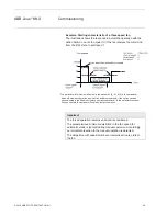
Page 48: ...l Actuator evaluates the threshold values in ascending order i e first of all the threshold value for OFF Fan speed 1 is checked followed by Fan speed 1 Fan speed 2 etc The correct method of function is only assured if the threshold value for OFF Fan speed 1 is less than the threshold value Fan speed 1 Fan speed 2 and this is less than Fan speed 2 Fan speed 3 etc Object value Automatic On Off swit...

Page 49: ...curs Threshold value speed 2 speed 3 in 1 100 Options 1 70 100 Here the threshold value at which switch over to fan speed 3 occurs is set If the value in the communication object Control value HEATING or Control value COOLING is greater than the parameterised threshold value switch over to fan speed 3 occurs Hysteresis threshold value in 0 20 Options 0 5 20 Here a hysteresis is set at which switch...

Page 50: ...transition occurs the new speed is determined using the control value and the set switch thresholds The hysteresis is not considered 3 A control variable with the value 0 always results in speed 0 An example Parameterised Threshold value OFF speed 1 10 Threshold value 1 speed 2 20 Threshold value 2 speed 3 30 Hysteresis 15 Behaviour when ascending from speed 0 Speed 0 transition at 25 10 hysteresi...

Page 51: ...dby operation Speed ranges limitations are defined for the fan with the speed limitation function that may not be exceeded or undershot Four limitations are available This can be used for example for the control of various operating modes e g frost heat protection comfort night shut down and standby In normal cases the thermostat takes these operating modes into account in its control variable for...

Page 52: ...trol is also possible x The limitation is activated if a telegram with the value 1 is received on the limitation object The limitation is deactivated if a telegram with the value 0 is received on the limitation object A manual action ends automatic mode x If a limitation is activated the Fan Coil Actuator switches to the parameterised fan speed regardless of the control value If during the activat...

Page 53: ...ter you set the fan speed that is set with active limitation or the speed that is not exceeded or undershot x 3 2 1 OFF everything is possible x Unchanged the state is retained x OFF Off x 1 limited to speed 1 x 1 OFF limited to speed 1 and off x 2 limited to speed 2 x 2 1 limited to speed 2 and 1 x 2 1 OFF limited to speed 2 1 and off x 3 limited to speed 3 x 3 2 limited to speed 3 and 2 x 3 2 1 ...

Page 54: ...alue 1 fan speed x is switched on 0 fan speed x is switched off If several ON OFF telegrams are received consecutively in a short period of time at various Fan speed 1 3 communication objects the value last received by the fan control is the decisive value An OFF telegram to one of the three communication objects Fan speed 1 3 switches off the fan completely Important The forced operation remains ...

Page 55: ...utomatic mode is ignored during manual operation Accordingly an immediate reaction to the manual operation is detected The delay time with speed switch over remains active to protect the fan With multiple manual UP or DOWN switching the target speed will be increased or reduced by a speed step This is possible until the maximum or minimum possible speed is achieved Further UP or DOWN telegrams are...

Page 56: ... 1M the following parameters must be set x In the Fan parameter window the option multi level must be selected for the Fan type parameter x The parameter Speed on 2 limit must be selected with yes Now a two speed fan is controlled via fan speeds 1 and 2 Fan speed 3 with all its parameters and options is now non functional Note Further parameters and their setting possibilities are described in par...

Page 57: ...Option multi level one level The fan type to be controlled is set with this parameter If a fan with up to three speeds is to be controlled the option multi level must be selected If a fan with one speed is to be controlled the option one level must be selected Fan speed on bus voltage failure Option unchanged OFF ON The behaviour of the fan on bus voltage failure is defined here ...

Page 58: ...able to apply a bus voltage before connecting the fan in order to achieve a defined switch state of the fan This eliminates the possibility of the destruction of the fan due to an incorrect contact setting Enable communication objects Forced operation 1 bit Options no yes x yes A 1 bit Forced operation communication object is enabled Further parameters appear at the same time Forced operation on o...

Page 59: ...n minimum time the following parameters appear Time in s 1 65 535 Options 1 20 65 535 The fan remains ON for at least this time Function time on OFF Options none switching delay minimum time The function Time at fan OFF is defined with this x none No Time function is executed x switching delay The fan is switched off using this delay x minimum time The fan remains OFF for at least this time With o...

Page 60: ...automatic forced operation and the four limitations are indicated directly via a 1 bit coding For further information see Status byte Forced operation page 157 With the option yes two further parameters appear Send object value Options no update only after a change after request after a change or request x no update only The status is updated but not sent x after a change The status is sent after ...

Page 61: ...nication object With the option yes two further parameters appear Send object value Options no update only after a change after request after a change or request x no update only The status is updated but not sent x after a change The status is sent after a change x after request The status is sent after a request x after a change or request The status is sent after a change or a request The follo...

Page 62: ...ate only after a change after request after a change or request x no update only The status is updated but not sent x after a change The status is sent after a change x after request The status is sent after a request x after a change or request The status is sent after a change or a request ...

Page 63: ...eceives the value 1 if a fan speed is set If a fan speed is not set the communication object will receive the value 0 Object value Automatic On Off switch on to the automatic Options 1 0 This parameter defines how to react to a telegram x 1 Automatic is activated by a telegram with value 1 x 0 Automatic is activated by a telegram with value 0 Threshold value OFF ON in 1 100 Options 1 10 100 Here t...

Page 64: ... upper or lower threshold Example a three speed fan hysteresis with fan control Using hysteresis a continuous switching between the fan speeds around the threshold value with deviating input signals can be avoided Enable limitations Option no yes x yes Other parameters appear At the same time 4 communication objects for limitation of the fan speed are enabled x Limitation 1 e g for frost heat prot...

Page 65: ...ower limit of the fan limitation can be set at best When automatic mode is exited e g by a manual action the limitations 1 to 4 remain The following points apply for limitations x The fan speed and valve position can be parameterised independently x The limitation need not necessarily apply to one fan speed only It can also encompass another range of the fan speeds i e only certain fan speeds can ...

Page 66: ...peed with limitation 1 Fan speed with limitation 3 Options inactive unchanged OFF ON With this parameter you set which fan speed is set with active limitation or which speed is not exceeded or undershot Fan speed with limitation 2 Fan speed with limitation 4 Options inactive unchanged OFF ON With this parameter you set which fan speed is set with active limitation or which speed is not exceeded or...

Page 67: ...arameter Valve control Valve control Options Continuous PWM 3 point opening and closing With this parameter the properties of the connected valve are set Pulse width modulation PWM page 142 Observe reversing time Options no 100 300 500 700 1 000 ms A reversing time pause is set via this parameter The time should be taken from the technical data of the valve Valve position on bus voltage failure in...

Page 68: ... open The time should be taken from the technical data of the valve Correct valve characteristic curve Option no yes If the option yes is set in the parameter the parameter window Curve page 76 in which the valve is set appears Automatically adjust valve position Option no yes x yes Furthermore the parameters Number of valve controls up to adjustment 1 65 535 appears x no Nothing happens Note A ma...

Page 69: ... been undertaken If priorities and curves prevent this the adjustment counter will not change Reference movement A reference movement can be understood as a complete closing of the valve Referencing is undertaken after x Every reset of the bus x A change of version x Every reset of an un parameterised device x A download with modified adjustment time The following should be considered x Referencin...

Page 70: ...set How does a de energised closed normally closed valve behave If no current flows in the control circuit the valve is closed The valve is opened as soon as current flows in the control circuit How does a de energised opened normally open valve behave If no current flows in the control circuit the valve is opened The valve is closed as soon as current flows in the control circuit x de energised c...

Page 71: ... the valves after bus voltage recovery can be set in percent Cycle time of the PWM in s 10 6 000 Option 10 180 6 000 This is used to set the cycle time of the PWM control Important The minimum pulse length is defined as 0 5 seconds so that with very short cycle times 1 min there are very short switch on times with small percentage values or switch off times with higher percentage values Valve cont...

Page 72: ...ved The difference between the current and the new control value is ascertained for determination of the additional time The additional time is dependent on how large the control value change should be from the current control value to the new control value Example If the change in the control value ascends i e the current control value is at 10 and the new control value is at 20 fast heat up is a...

Page 73: ...ation object Block is enabled and can then be used for blocking With option yes the following parameters appear Disable on object value Options 1 0 Here you set the object value used to block the valve Enable communication object Forced operation 1 bit Options no yes x yes The 1 bit communication object Forced operation is enabled and can then be used for forced operation Note The characteristic c...

Page 74: ...on Enable communication object Status valve position Options no 1 bit 1 byte Note The valve position status is sent immediately after the control value is received x 1 bit The following parameters appear Send object value Options no update only after a change after request after a change or request x no update only The status is updated but not sent x after a change The status is sent after a chan...

Page 75: ... If the valve purge is interrupted by a higher priority it will restart after the completion of the priority task unless i e the control value was 100 or it was active for the duration of the purge time due to the higher priority The valve position for purging is always the control value 100 A correspondingly matched curve is considered For further information see Priorities with page 153 With opt...

Page 76: ...e time duration for the valve purge is set with this parameter In this time the valve is fully opened When the time has elapsed the state before the purge is re established Note The opening time of the valve must be considered when entering the purge time The characteristic curve adjustment is active for the valve purging time Automatic valve purge Options no yes x yes The following parameters app...

Page 77: ...e After bus voltage recovery and download the purge cycle continues the bus failure time the time for which the bus actually failed is not considered The purging cycle will restart if Purge cycle in weeks 1 12 is changed after the download Reset purge cycle from control value in 1 99 Options 1 99 Hereby the purge cycle from the set control value is reset ...

Page 78: ...est value position applies All other value pairs are ignored x The value pair with the smallest valve position applies for the correction of the smaller control values x If no value pair has been entered for the control value 0 the valve position of the first value pair applies for all control values from 0 to the first value pair x If no value pair has been entered for the control value 100 the v...

Page 79: ...rve The possibility of activating other value pairs allows different curve characteristics to be realised For further information see Curve page 138 A total of four value pairs can be set Further value pair Options no yes x yes A further value pair can be set Value pair 3 Control value in 0 100 Options 0 50 100 Valve position in 0 100 Options 0 50 100 Further value pair Options no yes x yes A furt...

Page 80: ...COOLING The setting options of valve COOLING do not differentiate from those of valve HEATING The descriptions of the parameter setting options and adjustable communication objects for the valve COOLING are described under parameter window Valve HEATING 3 point opening and closing page 65 ...

Page 81: ... short and long operation x yes After opening closing of the contact it must first of all be ascertained if a short or long operation has occurred here Only thereafter will a possible reaction be triggered The following drawing shows the function in detail Without distinction between short long With distinction between short long TL Input signal Possible reaction to the input signal Possible react...

Page 82: ...ration the following parameters in the parameter window Input A are visible Reaction on closing the contact rising edge Options ON OFF TOGGLE no reaction terminate cyclic sending Reaction on opening the contact falling edge Options ON OFF TOGGLE no reaction terminate cyclic sending For each edge a definition is made to determine if the object value ON OFF or TOGGLE is switched or if there should b...

Page 83: ...ned The input reacts as if the state on the input terminals has just been set not set Note The inactive waiting time does not add to the actual adjustable send delay time This can be set separately Debounce time Options 20 30 50 70 100 150 ms Debouncing prevents unwanted multiple operations of the input e g due to bouncing of the contact What is the debounce time If an edge is detected at an input...

Page 84: ...in principle to start cyclic sending by sending a value to the communication object Switch As this behaviour is generally unwanted the flags Write and Update of the communication object are deleted in the preliminary setting so that they cannot be changed via the bus If this functionality is still required however these flags should be set accordingly With changes to the Switch communication objec...

Page 85: ...on will commence No telegram is sent on the bus at this time The signal on the input is observed within the minimum signal duration If a further edge appears at the input during the minimum signal duration it will be interpreted as a new operation and the minimum signal duration restarts If the input signal duration has not changed during the minimum signal duration an edge is detected and a teleg...

Page 86: ...er window Input A are visible Reaction on short operation Options ON OFF TOGGLE no reaction Reaction on long operation Options ON OFF TOGGLE no reaction For each edge a definition is made to determine if the object value ON OFF or TOGGLE is switched or if there should be no reaction Long operation after Options 0 3 0 4 0 5 0 6 0 8 s 1 1 2 1 5 s 2 3 4 5 6 7 8 9 10 s Here the time period TL after wh...

Page 87: ...ed multiple operations of the input e g due to bouncing of the contact What is the debounce time If an edge is detected at an input the input will react immediately to this edge e g by sending a telegram At the same time the duration of the debounce time TD starts The signal on the input is not evaluated within the debounce time duration Example Debounce time of the input signal for a detected edg...

Page 88: ... STOTZ KONTAKT GmbH 86 3 2 10 Parameter window Input B Input B does not differentiate from input A The descriptions of the parameter setting options and adjustable communication objects for the Input B are described under Input A page 78 ...

Page 89: ...ct An ON telegram 1 closes the contact and an OFF telegram 0 opens the contact x Normally closed contact An ON telegram 1 opens the contact and an OFF telegram 0 closes the contact Contact position on bus voltage failure Options opened closed unchanged The output can adopt a defined state on bus voltage failure using this parameter x opened The contact is opened with bus voltage failure x closed T...

Page 90: ... to be monitored The Fan Coil Actuator draws the energy for switching the contact from the bus After bus voltage is applied sufficient energy is only available after about ten seconds in order to switch all contacts simultaneously Depending on the set transmission and switching delay after recovery of bus voltage set in the parameter window General the individual outputs will only assume the desir...

Page 91: ...x after a change or request The status is sent after a change or a request Object value of contact position Object Status Switch Options 1 closed 0 open 0 closed 1 open With this parameter the communication object value of the switch status Status Switch is defined x 1 closed 0 open A closed contact is represented by communication object value 1 and an open contact is represented by the value 0 x ...

Page 92: ...Options unchanged 1 i e Disable function Time 0 i e Enable function Time x unchanged The function Time can continue unchanged x 1 i e Disable function Time The function Time is disabled Note They can only be enabled via the communication object Function time disable x 0 i e Enable function Time The function Time is enabled and active after a bus failure Note If the staircase light is disabled when...

Page 93: ...ble Enable communication object Change duration of staircase lighting 2 byte Options no yes x yes A 2 byte Change duration of staircase lighting communication object is enabled The staircase lighting time can be changed via the bus with this The value defines the staircase lighting time in seconds The staircase lightning time which has already commenced is completed A change of the staircase light...

Page 94: ...f the communication object Switch and remains switched on until the communication object Permanent ON has the value 0 After ending the Permanent ON state the staircase will react as defined in the following parameters Example This communication object can be used for example to allow the caretaker or maintenance and cleaning personnel to initiate a permanent ON The following parameter is visible i...

Page 95: ...The manual switchover button hand symbol must be pressed to light up the respective LED Thereafter the device can be operated via the foil keypad It is thus possible to try out all functions of the Fan Coil Actuator via the buttons before the complete installation is put into operation e g you can test if the fan speed switches UP and DOWN to suit the fan speed If the manual switchover button is p...

Page 96: ...re sent on the bus as long as these have not been programmed with the option after a change or request The following function results for the option x 1 Telegram value 1 all status messages are sent provided they are programmed with the option after a change or request 0 nothing happens 2 5 Manual operation See description Manual operation page 95 6 Overload Valve HEATING EIS 1 1 bit DPT 1 005 C R...

Page 97: ...ng the states of the inputs and outputs are transferred to the input terminals If the value 1 is in this communication object then the Fan Coil Actuator is switched over to bus operation Telegram value 0 enable button 1 block button 3 LED ON OFF Manual operation EIS 1 1 bit DPT 1 001 C W Using this communication object the LED ON OFF is controlled on the foil keypad Telegram value 0 LED OFF 1 LED ...

Page 98: ...is predefined as a 1 byte value Telegram value 0 OFF no heating or cooling 100 ON largest control value maximum heating or cooling 31 Control value COOLING extra Control input EIS 6 1 byte DPT 5 001 C W Note Independent of communication object 30 the COOLING valve can be additionally controlled without monitoring via the communication object 31 The communication object is enabled if in parameter w...

Page 99: ...OOLING is predefined as a 1 byte value Telegram value 0 OFF no heating or cooling 100 ON largest control value maximum heating or cooling 31 not assigned 32 Toggle HEATING COOLING Control input EIS 1 1 bit DPT 1 100 C W The communication object is enabled if in parameter window Control input the parameter HVAC System has been selected with the option 1 Control values 4 pipe with switching object I...

Page 100: ...s 2 pipe Using this communication object the control value HEATING is predefined as a 1 byte value Telegram value 0 OFF no heating 100 ON largest control value maximum heating 31 Control value COOLING Control input EIS 6 1 byte DPT 5 001 C W The communication object is enabled if in parameter window Control input the parameter HVAC System has been selected with the option 2 Control values 2 pipe U...

Page 101: ...on object is enabled if in parameter window Control input the parameter HVAC System has been selected with the option 2 Control values 2 pipe with switching object Using this communication object the control value COOLING is predefined as a 1 byte value Telegram value 0 OFF no cooling 100 ON largest control value maximum cooling 32 Toggle HEATING COOLING Control input EIS 1 1 bit DPT 1 1000 C W Th...

Page 102: ...s 2 pipe Using this communication object the control value HEATING is predefined as a 1 byte value Telegram value 0 OFF no heating 100 ON largest control value maximum heating 31 Control value COOLING Control input EIS 6 1 byte DPT 5 001 C W The communication object is enabled if in parameter window Control input the parameter HVAC System has been selected with the option 2 Control values 2 pipe U...

Page 103: ...mmunication object indicates a malfunction of the control value e g of a thermostat The Fan Coil control reports a fault and assumes the safety position with the communication object Fault control value This safety position affects the fan speed and the valves Telegram value 0 no fault 1 fault Note If the object value Control value HEATING Control value COOLING or Control value HEATING COOLING rem...

Page 104: ... of a fan speed If another fan speed is switched on at this point it will be switched off A new fan speed is switched on taking the transition times dwell times and start up phase into consideration Limitations through forced operation or one of the four limitations 1 4 are retained Automatic operation is disabled A renewed activation of automatic mode occurs via the communication objects Automati...

Page 105: ...tic operation is disabled A renewed activation occurs via the communication objects Automatic ON OFF If several 1 ON telegrams are received by the various speed objects the value last received for the fan control is decisive The same applies for the OFF telegram 0 If the actuator for the switched off fan speed again receives an OFF command it is carried out i e another speed switched on at this ti...

Page 106: ...rams are ignored and not executed Each new switching telegram initiates a new calculation of the target speed Telegram value 0 switch fan speed DOWN 1 switch fan speed UP 15 Status fan ON OFF Fan EIS 1 1 bit DPT 1 001 C T The communication object is enabled if in parameter window Status messages the parameter Enable communication object Status Fan ON OFF 1 bit has been selected with the option yes...

Page 107: ...for the 1 byte object Figure value Hexadecimal Binary value bit 76543210 Fan speed 0 00 00000000 0 OFF 1 01 00000001 Fan speed 1 2 02 00000010 Fan speed 2 3 03 00000011 Fan speed 3 17 Status fan speed 1 Fan EIS 1 1 bit DPT 1 001 C R T The communication object is enabled if in parameter window Status messages the parameter Enable communication object Status fan speed x 1 bit is selected with option...

Page 108: ...eived on the communication object Limitation 1 The Limitation 1 is deactivated if a telegram with the value 0 is received on the communication object Limitation 1 When Limitation 1 is activated the fan can only assume the set fan speed or fan speed range in the parameter window Fan B Limitation The valve position is independently programmable from the fan limitation Telegram value 0 limitation x i...

Page 109: ... If automatic mode is enabled it will be activated on this communication object with the value 1 after a download bus reset or via a telegram Automatic mode is switched off if a signal is received on a manual communication object During forced operation the automatic mode remains active however it is only operated within the allowed limits If the value 1 is set in the parameter Telegram value 0 au...

Page 110: ...hen changed Bit sequence 76543210 Bit 7 Forced operation Telegram value 0 inactive 1 active Bit 6 Limitation 1 Telegram value 0 inactive 1 active Bit 5 Limitation 2 Telegram value 0 inactive 1 active Bit 4 Limitation 3 Telegram value 0 inactive 1 active Bit 3 Limitation 4 Telegram value 0 inactive 1 active Bit 2 Thermostat fault Telegram value 0 inactive 1 active Bit 1 Automatic Telegram value 0 i...

Page 111: ...s 1 4 are retained Automatic operation is disabled A renewed activation occurs via the communication objects Automatic ON OFF If several ON telegrams 1 are received the value last received for the fan control is decisive This also applies for the OFF telegram 0 If the actuator for the switched off fan speed again receives an OFF telegram it is carried out i e another speed switched on at this time...

Page 112: ...ed Using the communication object Status fan ON OFF the fan can for example be switched on centrally with a switch actuator via the main switch 16 20 Not assigned 21 Limitation 1 Fan EIS 1 1 bit DPT 1 003 C W The communication object is enabled if in parameter window Automatic operation the parameter Enable limitations has been selected with the option yes The limitation 1 is active if a telegram ...

Page 113: ...enabled it will be activated on this communication object with the value 1 after a download bus reset or via a telegram Automatic mode is switched off if a signal is received on a manual communication object During one of the four limitations or forced operation the automatic mode remains active but however it is only operated in the allowed limits If the value 1 is set in the parameter Telegram v...

Page 114: ...hen changed Bit sequence 76543210 Bit 7 Forced operation Telegram value 0 inactive 1 active Bit 6 Limitation 1 Telegram value 0 inactive 1 active Bit 5 Limitation 2 Telegram value 0 inactive 1 active Bit 4 Limitation 3 Telegram value 0 inactive 1 active Bit 3 Limitation 4 Telegram value 0 inactive 1 active Bit 2 Thermostat fault Telegram value 0 inactive 1 active Bit 1 Automatic Telegram value 0 i...

Page 115: ...ation Valve HEATING EIS 1 1 bit DPT 1 003 C W This communication object sets the output in a defined state and blocks it If the value 1 is received forced operation is activated and the output triggers the programmed valve position If the value 0 is received forced operation ends The contact position is retained until the FCA S receives a new setting signal Telegram value 0 end forced operation 1 ...

Page 116: ...us of the valve position is visible via this communication object Hereby the target position where the valve should move to is always transferred The display LED HEATING indicates the same value as the status Telegram value 0 Valve position equal to zero LED HEATING off 1 Valve position not equal to zero LED HEATING on 39 Status valve position Valve HEATING EIS 5 1 byte DPT 5 001 C R T This commun...

Page 117: ...ING The valve COOLING does not differ from valve HEATING The descriptions of the parameter setting options and the adjustable communication objects for the valve COOLING are described in parameter window Valve HEATING page 65 or the communication objects Valve HEATING page 113 ...

Page 118: ...jects continue to be updated and sent if necessary When enabling an input a change of the signal states compared to before the block leads to immediate processing e g The minimum actuation or detection of a long short button push starts Communication objects are sent if necessary Telegram value 0 enable input 1 block input 51 Switch Input A EIS 1 1 bit DPT 1 001 C W T In accordance with the parame...

Page 119: ... This communication object is only visible if the parameter Distinction between long and short operation and Enable communication object with Long operation 1 bit has been selected with yes This additional communication object is assigned to the long actuation Communication object Input A Switch no longer reacts to a long operation Telegram value 0 no 1 yes ...

Page 120: ...18 3 3 9 Input B Input B does not differentiate from input A The descriptions of the parameter setting options and adjustable communication objects for the Input B are described under parameter window Input A page 79 and communication objects Input A page 116 ...

Page 121: ...munication object Permanent ON has the value 0 After ending the permanent ON state the state of the communication object Switch is used Permanent ON only switches ON and masks the other functions This means that the other functions e g staircase lighting time continue to run in the background but do not initiate a switching action After the end of permanent ON the switching state which would resul...

Page 122: ... 2 byte DPT 7 005 C R W This communication object is visible if in the parameter window Time the parameter Enable communication object Change duration of staircase lighting 2 byte has been selected with yes The staircase lighting time can changed via the bus using this communication object The time is defined in seconds The staircase lightning time which has already commenced is completed A change...

Page 123: ...up phase can be parameterised Up to two input variables for heating and cooling signals for example for a thermostat are available As output variables the Fan Coil Actuators generate up to two valve communication objects which they can use to control the valves in a heating or cooling circuit The separate fan and valve parameterisation in the FCA S provides a maximum in flexibility and very many c...

Page 124: ...n Coil Actuator The control of the FCA S is implemented in accordance with the following schematic principle With three Fan speed x switch x 1 2 or 3 communication objects that are independent of each other the fan speeds are controlled via the outputs of the Fan Coil Actuator Alternatively the fan control can be implemented via a 1 byte communication object Switch speed or via the communication o...

Page 125: ...0 Fan speed 1 1 0 0 Fan speed 2 0 1 0 Fan speed 3 0 0 1 4 1 2 2 Fan with speed switching In some cases the fan is controlled via a step switch The following control table results for a three speed fan which simulates the FCA S with its outputs Output 1 Output 2 Output 3 OFF 0 0 0 Fan speed 1 1 0 0 Fan speed 2 1 1 0 Fan speed 3 1 1 1 The step switch cannot be switched on rapidly If for example fan ...

Page 126: ...If two heat exchangers with two separate heating and cooling circuits are in use you have a 4 pipe system The Fan Coil Actuator directly controls the fan and provides one or two communication objects for control of the valves The heat exchanger and the fan are the most important components of a Fan Coil unit Heating or cooling water flows in the heat exchanger depending on the desired room tempera...

Page 127: ... by a motor The motor and the valves are controlled by a Fan Coil Actuator The water condensation which results during cooling collects in a condensation water trough 4 1 5 Pipe systems A Fan Coil unit can be configured as a 2 3 or 4 pipe system 4 pipe version 3 pipe version 2 pipe version ...

Page 128: ...s of just a single water circuit which is heated or cooled alternately to suit the season In a 2 pipe Fan Coil unit there is only one heat exchanger with a valve Note In some HVAC systems cooling is undertaken exclusively with a 2 pipe Fan Coil unit The heating function is undertaken by a conventional heater or an electrical heater ...

Page 129: ...g on the weather warm or cold water is supplied centrally to the pipe system 2 pipes The Fan Coil Actuator or the thermostat is informed if warm or cold water is currently flowing through the system Depending on this setting both control values act on just a single valve The thermostat decides which control value HEATING COOLING is actively sent The FCA S controls the fan speed and only one valve ...

Page 130: ... cold water is supplied centrally to the pipe system 2 pipes Depending on this setting one control value acts on one valve The thermostat sends the control value COOLING and the FCA S controls the fan speed and the valve Note Both 2 pipe systems can be established using a 3 speed fan or blower Depending on the control value 1 byte or 1 bit which is sent from a thermostat the Fan Coil Actuator dete...

Page 131: ...peed 2 30 59 Fan speed 1 2 30 Fan speed 3 60 100 Fan speed 2 3 60 4 1 5 4 3 pipe system configuration The 3 pipe system has a similar design to the 4 pipe system There is a separate inlet for heating and cooling water as well as two separate heat exchangers with one valve each In contrast to a 4 pipe system the 3 pipe system has a common return for heating and cooling water The Fan Coil Actuator d...

Page 132: ...tems of 2 pipes each The thermostat onsite decides if heating or cooling is applied The thermostat sends either a separate heating and cooling signal or a common heating cooling signal If only one signal is sent for HEATING and COOLING an additional signal decides if the system is in heating or cooling mode and the valve that has to be controlled The Fan Coil Actuator directly controls the fan and...

Page 133: ...ction is undertaken by a thermostat Even the offset of the set point value as well as changeover of the operating modes is implemented by the thermostat The sensors can be connected directly to the Fan Coil Actuator in order to consider the monitoring of the condensed water and the window contact In order to correctly implement this function the thermostat must send the actual temperature as well ...

Page 134: ...he object Control value HEATING COOLING are available The automatic mode is enabled in the parameter window Fan with the parameter Enable automatic operation Depending on the HVAC system this is set in the parameter window Control input and the control value objects are enabled An automatic operation parameterised in the ETS only becomes active after the first download With a subsequent download t...

Page 135: ...ABB i bus KNX Planning and application 2010 ABB STOTZ KONTAKT GmbH 133 The following functional diagram shows the relationship between automatic and manual operation of the Fan Coil Actuator ...

Page 136: ...he received 1 byte value to the fan speed occurs as with the automatic fan control via the parameterised threshold values 1 byte value Fan speed 0 9 0 fan off 10 39 1 40 69 2 70 100 3 4 2 3 Switchover between automatic and direct operation In the Fan Coil Actuator you can switch between automatic operation and direct operation The changeover to manual fan control is implemented via a 1 bit value T...

Page 137: ...ates the logic of a switchover speed for a Fan Coil Actuator in dependence on the control values and the parameterised threshold values and hysteresis The diagram relates to a three speed fan without parameterised fan limitations The fan limitations are only relevant after the fan speed has been determined and do not change the flow chart ...

Page 138: ...an operation functional diagram The following illustration indicates the sequence in which the functions of the fan control are processed Communication objects which lead to the same box have the same priority and are processed in the sequence in which the telegrams are received ...

Page 139: ...ve drives the valve can be opened by any desired percentage and the position can be retained over an extended period If the valve does not move no voltage is applied to the motor The valve is opened wide enough to allow the exact quantity of hot or cold water to flow that is required to bring the heat exchanger to the required temperature Thus the valve is controlled via the valve opening 0 100 Th...

Page 140: ...rol value of 0 i e also 0 The valve is fully open with a control value of 100 i e also 100 The same ratio also applies for all intermediate values Linear valve curve These valve curves can be matched for different valve types Many valves for example have practically no flow when barely opened and achieve maximum flow at 60 80 Furthermore many valves emit an annoying whistling sound at low flows Va...

Page 141: ...an be taken into consideration by limitation of the active valve opening range The positioning frequency of the valve drive may also be reduced by this limitation Limitation of the active valve opening range 0 100 Valve position Valve control value 0 100 Active valve opening range 30 80 ...

Page 142: ...ndow Curve page 76 that is separately adjustable for the heating and the cooling valve The valve control value can be adapted to the control value using the adjustable parameters there The positioning frequency of the valve drive may also be reduced by this function A reduction of the positioning frequency reduces the current requirement for positioning and increases the service life of the valve ...

Page 143: ...ch complies with the calculated control value With this method the valve can be fully opened fully closed and even positioned in every intermediate position With continuous control the most accurate control of the temperature can be achieved without any resulting overshoots At the same time the positioning frequency of the valve drive can be kept low Continuous control can be implemented with the ...

Page 144: ...ted in the duration for valve opening The control value 20 at a cycle time of 15 minutes for example will be recalculated for a valve opening time of three minutes The control value 50 results in a valve opening time of 7 5 minutes With pulse width modulation a relatively accurate control of the temperature can be achieved without any resulting overshoots Simple attractively priced control valves ...

Page 145: ...M calculation is converted into a signal for a 2 point control ON OFF value With PWM control the received control value 0 100 calculated in the control algorithm is converted to a pulse width modulation The conversion is based on a constant cycle time If the FCA S for example receives a control value of 20 then for a cycle time of 15 minutes the valve will be opened for three minutes 20 of 15 minu...

Page 146: ...lation calculation With pulse width modulation the control is implemented by a variable mark space ratio During the time tON the valve is opened and during the time tOFF it is closed Due to tON 0 4 x tCYC the valve is set to about 40 on tCYC is the so called PWM cycle time for continuous control ...

Page 147: ...on known to the Fan Coil Actuator x The send delay is only active at bus voltage recovery Switch contact output x The object value Staircase lighting time remains unchanged as before bus voltage failure x The object value Disable function time is independent of the selected option x The object value Permanent ON remains unchanged as before bus voltage failure x The switch contact output switches a...

Page 148: ...t 2 Manual operation 3 Communication object Block 4 Communication object Forced operation 5 Valve purge 6 Adjustment 7 Control values Note 1 corresponds to the highest priority x The value parameterised for bus voltage recovery is only carried out if no higher priority with the exception of manual operation reference run was active before the failure If during bus voltage recovery and an active pr...

Page 149: ...ram and it is restarted Switch contact output x The object value Staircase lighting time receives its parameterised value x The object value Disable function time is 0 i e the function Time is not blocked x The object value Permanent ON is 0 i e Permanent ON is not active x The switch contact output goes to the safely opened state Note For all resets after delivery including the first download the...

Page 150: ...is not influenced Object values remain unchanged Timer will not operate and must only be restarted Status values are updated and sent The contact position remains unchanged and only changes with the next switch command Note After a download with a change the application complies in behaviour to a reset of the device in the ETS If the application of the same version is reloaded after discharge the ...

Page 151: ...ge recovers Only the energy for a non delayed switching action is available when the bus voltage fails for each output Reversing times dwell times and start up behaviour cannot be considered For this reason it is only possible for the fan at bus voltage recovery to retain the fan speed unchanged or to switch off The special behaviour is described in the following table 4 4 5 Behaviour with bus vol...

Page 152: ...when the next telegram is received Unchanged and sent Values are updated and sent in dependence on the parameterisation Bus voltage failure Can be parameterised no function Fan speed as parameterised with BVF no function Fan speed as parameterised with BVF no function no function no function no function no function Bus voltage recovery Can be parameterised Inactive Inactive Automatic mode is activ...

Page 153: ...ctive after a down load Bus voltage failure Communication object no longer available Communication object no longer available Timer stops Contact position parameterised with BVF no function Contact position with bus voltage failure can be parameterised no function Contact position with bus voltage failure can be parameterised Bus voltage recovery Can be parameterised Can be parameterised In the pa...

Page 154: ...hanged Monitoring time will be restarted Object value unchanged Inactive Monitoring time restarts Bus voltage failure Can be parameterised Unchanged however without function Contact position is programmable No monitoring Inactive Time is lost No purging Bus voltage recovery Can be parameterised Unchanged Monitoring time will be restarted Object value is 0 Inactive must be reactivated Monitoring ti...

Page 155: ...Priorities with 4 5 1 Valve HEATING COOLING The priorities are defined as follows 1 Reference movement 2 Manual operation 3 Communication object Block 4 Communication object Forced operation 5 Valve purge 6 Adjustment 7 Control values Note 1 corresponds to the highest priority ...

Page 156: ...of the PWM at the new valve position x Tcyc PWM cycle time x T 1 Is added on the way to Vnew at every position passed through Calculation of the closing time Calculation of the closing time at switchover new act act new atV T atV T atV T T T 1 1 1 1 This means x For a movement from 0 99 the contact remains closed for about Tup Tcyc x For a change in the lower range it results in significantly shor...

Page 157: ...the new valve position x Tcyc PWM cycle time x T 1 Is added on the way to Vnew at every position passed through Calculation of the opening time Calculation of the opening time at switchover new act act new atV T atV T atV T T T 1 1 1 1 This means x For a movement from 99 0 the contact remains opened for about Tdown Tcyc x For a change in the lower range it results in significantly shorter opening ...

Page 158: ......

Page 159: ...f delivery The Fan Coil Actuator is supplied together with the following components The delivered items should be checked according to the following list x 1 x FCA S 1 1M Fan Coil Actuator MDRC x 1 x installation and operating instructions x 1 x bus connection terminal red black ...

Page 160: ...10 6E 196 C4 25 19 111 6F 197 C5 26 1A 112 70 198 C6 27 1B 113 71 199 C7 28 1C 114 72 200 C8 29 1D 115 73 201 C9 30 1E 116 74 202 CA 31 1F 117 75 203 CB 32 20 118 76 204 CC 33 21 119 77 205 CD 34 22 120 78 206 CE 35 23 121 79 207 CF 36 24 122 7A 208 D0 37 25 123 7B 209 D1 38 26 124 7C 210 D2 39 27 125 7D 211 D3 40 28 126 7E 212 D4 41 29 127 7F 213 D5 42 2A 128 80 214 D6 43 2B 129 81 215 D7 44 2C 1...

Page 161: ... 2010 ABB STOTZ KONTAKT GmbH 159 A 3 Ordering information Short description Designation Order No bbn 40 16779 EAN Price group Weight 1 pc kg Packaging pc FCA S 1 1M Fan Coil Actuator MDRC 2CDG 110 084 R0011 66508 7 26 0 1 1 ...

Page 162: ...ABB i bus KNX Appendix 2010 ABB STOTZ KONTAKT GmbH 160 Notes ...

Page 163: ......

Page 164: ...right to make technical changes or modify the contents of this document without prior notice With regard to purchase orders the agreed particulars shall prevail ABB AG does not accept any responsibility whatsoever for potential errors or possible lack of information in this document We reserve all rights in this document and in the subject matter and illustrations contained therein Any reproductio...

Reviews: