KNX Technical Reference Manual
ABB-i-Bus
®
-KNX Millenium
Installation and electrical
connection
KNX Technical Reference Manual | 1473-1-8681
— 18 —
Pos: 18.8 /Layout bis 2014-11-11/Online-Dokumentation (+KNX)/Überschriften (--> Für alle Dokumente <--)/2. Ebene/M - O/Montage @ 18\mod_1302615960458_15.docx @ 103424 @ 2 @ 1
6.3
Mounting
Pos: 18.9 /Layout bis 2014-11-11/Online-Dokumentation (+KNX)/Montage und elektrischer Anschluss/KNX/KNX-Sensorik/Millenium/6124 - Raumtemperaturregler/Montage -- 6124 @ 31\mod_1351257089091_15.docx @ 243854 @ 3 @ 1
6.3.1
Installing the unit
The devices with integrated bus coupler have been prepared for installing in flush-mounted boxes according to
BS 4662:2006+A1:2009 in connection with the corresponding support ring and cover frame (see also chapter
"Cover frame and support ring", on page 13).
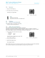
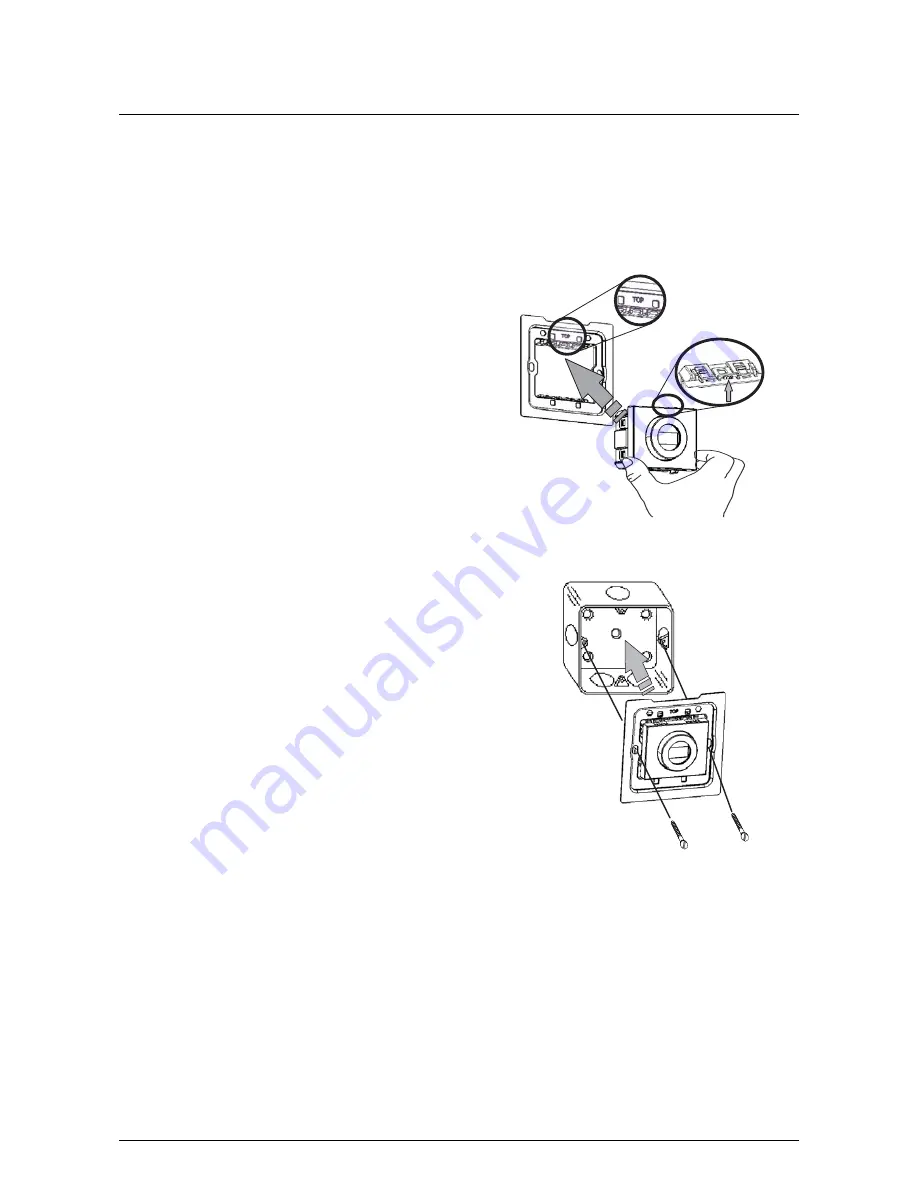
1. The side of the support ring with the marking "TOP" must
be aligned toward the top. Now insert the device into the
support ring in such a way that both sides with the
marking "TOP" (on the device and the support ring) are
aligned parallel to each other.
Fig. 4:
Inserting the device into the support ring
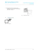
2. The connection to the KNX bus line is made with the
enclosed bus connection terminal (see also chapter
"Commissioning", section "Software" on page 20). Now
install the support ring with the inserted device in the
flush-mounted box ("TOP" toward the top) and screw it on
securely.
Fig. 5:
Inserting into the flush-mounted box
TOP


