ABB i-bus
®
KNX
Device technology
© 2008 ABB STOTZ-KONTAKT GmbH
20
2.2
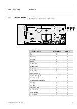
Connection schematics
Hotel room example
RM/S 2.1 with electromotor valve drives
1
Label carrier
2
Programming
button
3
Programming
LED
4
Bus terminal connection
5
Switch position display and manual operation, output (A, B, C) 20 A (16 AX)
6
Switch position display and manual operation, output (D) 16 A (10 AX)
7
Load circuits, with 2 terminals each
8
Outputs, 3 contacts, 1 screw terminal for phase connection (E, F, G)
9
Outputs, 3 contacts, 1 screw terminal for phase connection (H, I, J)
10
Shutter (K)
11
Fan (L, M, N)
12
Valve HEATING (O, P)
13
Valve COOLING (Q, R)
14
Outputs, 3 contacts, 1 screw terminal for phase connection (S, T, U)
15
Binary inputs (j, k, l, m, n, o, p, q, r)
16
Binary inputs (a, b, c, d, e, f, g, h, i)
2CDC 072
203
F00
08


