background image

ABB i-bus

®

 KNX 

Planning and application 


© 2008 ABB STOTZ-KONTAKT GmbH 


233 


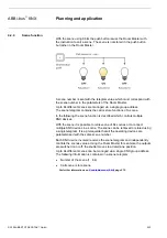
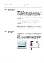
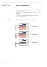
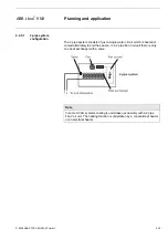
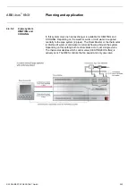
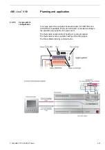
The current position of the sun is calculated based on the time of day.  
The Shutter Control Unit can be operated as an independent clock, as a 
master clock or as a slave clock on the KNX. Several shutter control units 
can also be synchronised together. If the Shutter Control Unit is operated  
as an independent clock or as a master clock, no further time switches are 
required. 

The Shutter Control Unit can likewise be operated as a slave clock if for 
example a master clock is present in the installation. A time switch which can 
send the time and date on the KNX must be used as a master clock. 


4.3.3.2 

Status feedback 

Position in [0…100] 

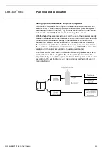
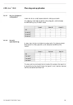
The Room Master can feedback the position of the shutter on the bus as an 
8 bit value via the same communication object used to call the position.  
The corresponding group address should be defined in the ETS as the 
“sending group address”.  


Summary of Contents for i-bus KNX Room Master Premium RM/S 2.1

Page 1: ...ABB i bus KNX Room Master Premium RM S 2 1 Intelligent Installation Systems ABB Product Manual ...

Page 2: ...lusion of liability Despite checking that the contents of this document match the hardware and software deviations cannot be completely excluded We therefore cannot accept any liability for this Any necessary corrections will be inserted in new versions of the manual Please inform us of any suggested improvements ...

Page 3: ...puts 27 3 2 Parameters 28 3 2 1 Parameter window General 29 3 2 2 Parameter window Enable Inputs a f 32 3 2 2 1 Parameter window a Switch Sensor 34 3 2 2 1 1 Parameter Distinction between short and long operation no 36 3 2 2 1 2 Parameter Distinction between short and long operation yes 41 3 2 2 1 3 Special function Fault monitoring input 42 3 2 2 2 Parameter window a Dim Sensor 44 3 2 2 3 Paramet...

Page 4: ...l input 141 3 2 7 1 HVAC System 1 Control value 2 pipe 143 3 2 7 2 HVAC System 1 Control value 4 pipe with switching object 144 3 2 7 3 HVAC System 2 Control values 2 pipe 145 3 2 7 4 HVAC System 2 Control values 2 pipe with switching object 146 3 2 7 5 HVAC System 2 Control values 4 pipe 148 3 2 8 Parameter window O P Valve HEATING 0 5 A AC 3 point opening and closing 149 3 2 9 Parameter window O...

Page 5: ...s 224 4 3 2 1 Travel times 224 4 3 2 2 Safety 226 4 3 2 3 Determination of the current position 227 4 3 2 4 Move to position in 0 100 227 4 3 3 Automatic control 228 4 3 3 1 Automatic sun protection 228 4 3 3 2 Status feedback 233 4 4 Heating ventilation climate control with Fan Coil units 234 4 4 1 Terms 234 4 4 2 Fan operation 235 4 4 2 1 Fan in a changeover configuration 236 4 4 2 2 Fan with sp...

Page 6: ... 4 7 3 Download 261 4 7 4 Reaction on bus voltage failure 262 4 8 Priorities with 262 4 8 1 Valve HEATING COOLING 262 4 9 Fast heat up cool down 263 4 9 1 Heat up 263 4 9 2 Cooling down 264 4 10 Assembly of a distribution board with the Room Master Premium 265 A Appendix 267 A 1 Scope of delivery 267 A 2 Status byte fan forced operation 268 A 3 Status byte shutter blinds 269 A 4 Code table scene 8...

Page 7: ...pact form Switch lighting Control heating cooling Shading using shutters or curtains Switching of electrical sockets and loads In addition to these basic functions further automation functions can be implemented by a combination with a presence detector The communication of the devices via the KNX bus also enables control functions as well as sending of emergency signals from the rooms to a contro...

Page 8: ...dvantages of the Room Master are obvious not just during operation but also for planning world wide use compact design can be installed in a simple in distribution board together with circuit breakers see Assembly of a distribution board with the Room Master Premium page 265 a standard solution for many projects 1 1 2 Hospitals When used in hospitals and buildings with a similar purpose the Room M...

Page 9: ...ages to the control station e g emergency signals fast localisation of faults in the rooms indication of room states in the control station day night service 1 1 4 Apartments Apartments gain in both their appeal and the quality of life they offer with the Room Master decisive factors for sale and rental automatic switching of different lighting arrangements in the room automatic control of heating...

Page 10: ... requirements The Room Master is a modular installation device with a module width of 12 space units in ProM Design for installation in the distribution board The connection to the ABB i bus is established using the front side bus connection terminal The Room Master Premium does not require an auxiliary supply The assignment of the physical addresses as well as the parameterisation is carried out ...

Page 11: ...es are short circuit protected by self restoring fuses A changeover contact is available for control of a shutter or a curtain A separate floating contact is available for the connection of an auxiliary electrical heating system Nine outputs for direct connection of lighting circuits are provided These include lamps on the left right of the bed bathroom lamps entrance lighting two room illuminatio...

Page 12: ...hing of auxiliary heating door contacts card readers transmission of an emergency signal door bell for activation of Do not disturb Room service and Room occupied vacant The scanning voltage for the binary inputs is provided by the device The binary inputs are divided into six groups of three inputs each Overview of the number and allocation of the inputs and outputs Inputs RM S 2 1 Binary via con...

Page 13: ...itch Designation RM S 2 1 Hall a 1 Main room b 1 Bathroom c 1 Master d 1 Bedside left e 1 Bedside right f 1 Shutter open g 1 Shutter close h 1 Window contact I 1 Floor or desk light j 1 Bathroom blower k 1 Auxiliary electrical heater l 1 Drip tray m 1 Key card n 1 Emergency call o 1 Do not disturb p 1 Room service q 1 Living room r 1 ...

Page 14: ...6 A 10 AX switch Auxiliary electrical heater D 1 10 outputs with 6 A switch Light bedside left E 1 Light bedside right F 1 Light main room G 1 Light bathroom H 1 Light hall I 1 Light living room J 1 Shutter K 1 Fan L M N 3 4 outputs with 0 5 A switch Valve HEATING O P 2 Valve COOLING Q R 2 3 outputs with 6 A switch Display Do not disturb S 1 Display Room service T 1 Display Room occupied U 1 ...

Page 15: ...evice results from the following specifications KNX bus connection Relay 20 A Relay 16 A Relay 6 A Electronic outputs 0 5 A 0 25 W 3 0 W 1 0 W 2 4 W 1 0 W Connections KNX Via bus connection terminals 0 8 mm Ø solid Load circuits Ferrules without with plastic sleeves TWIN ferrules Tightening torque Screw terminals with universal head PZ 1 0 2 4 mm stranded 2 x 0 2 2 5 mm 0 2 6 mm single core 2 x 0 ...

Page 16: ...Approvals KNX to EN 50 090 1 2 Certification CE mark in accordance with the EMC guideline and low voltage guideline 2 1 1 Electronic outputs Rated values Number 4 non isolated short circuit proofed Un rated voltage 24 230 V AC 50 60 Hz In rated current per output pair 0 5 A Continuous current 0 5 A resistive load at TA up to 20 C 0 3 A resistive load at TA up to 60 C Inrush current Maximum 1 6 A 1...

Page 17: ...t peak may not be exceeded What do the terms AC1 AC3 and AC5a mean In Intelligent Installation Systems different switching capacity and performance specifications which are dependent on the special application have become established in industrial and residential systems These performance specifications are rooted in the respective national and international standards The tests are defined so that...

Page 18: ...erms AC1 AC3 and AC5a mean In Intelligent Installation Systems different switching capacity and performance specifications which are dependent on the special application have become established in industrial and residential systems These performance specifications are rooted in the respective national and international standards The tests are defined so that typical applications e g motor loads in...

Page 19: ... Mercury vapour lamp Uncorrected Parallel compensated 2000 W 2000 W Switching performance switching contact Maximum peak inrush current IP 150 μs 400 A Maximum peak inrush current IP 250 μs 320 A Maximum peak inrush current IP 600 μs 200 A Number of electronic ballasts T5 T8 single element 1 18 W ABB EVG 1 x 58 CF 23 24 W ABB EVG T5 1 x 24 CY 23 36 W ABB EVG 1 x 36 CF 14 58 W ABB EVG 1 x 58 CF 11 ...

Page 20: ...not be exceeded What do the terms AC1 AC3 and AC5a mean In Intelligent Installation Systems different switching capacity and performance specifications which are dependent on the special application have become established in industrial and residential systems These performance specifications are rooted in the respective national and international standards The tests are defined so that typical ap...

Page 21: ... CY 26 2 36 W ABB EVG 1 x 36 CF 22 58 W ABB EVG 1 x 58 CF 12 2 80 W Helvar EL 1 x 80 SC 10 2 1 For multiple element lamps or other types the number of electronic ballasts must be determined using the peak inrush current of the electronic ballasts 2 Limited by protection with B16 automatic circuit breakers Application program Maximum number of communication objects Maximum number of group addresses...

Page 22: ...tput A B C 20 A 16 AX 6 Switch position display and manual operation output D 16 A 10 AX 7 Load circuits with 2 terminals each 8 Outputs 3 contacts 1 screw terminal for phase connection E F G 9 Outputs 3 contacts 1 screw terminal for phase connection H I J 10 Shutter K 11 Fan L M N 12 Valve HEATING O P 13 Valve COOLING Q R 14 Outputs 3 contacts 1 screw terminal for phase connection S T U 15 Binary...

Page 23: ...20 A 16 AX 6 Switch position display and manual operation output D 16 A 10 AX 7 Load circuits with 2 terminals each 8 Outputs 3 contacts 1 screw terminal for phase connection E F G 9 Outputs 3 contacts 1 screw terminal for phase connection H I J 10 Shutter K 11 Fan L M N 12 Valve HEATING O P 13 Valve COOLING Q R 14 Outputs 3 contacts 1 screw terminal for phase connection S T U 15 Binary inputs j k...

Page 24: ...ABB i bus KNX Device technology 2008 ABB STOTZ KONTAKT GmbH 22 2 3 Dimension drawing 2CDC 072 054 F0008 ...

Page 25: ...ommissioning requirements In order to commission the device a PC with ETS from ETS2 V1 3a or higher as well as an interface to the ABB i bus e g via a KNX interface is required The device is ready for operation after connection to the bus voltage No additional auxiliary voltage is required The installation and commissioning may only be carried out by electrical specialists The appropriate norms gu...

Page 26: ...the PC which is used the progress bar for the download may take up to one and a half minutes before it appears due to the complexity of the device Assignment of the physical address The assignment and programming of the physical address is carried out in the ETS Cleaning If devices become dirty they can be cleaned using a dry cloth Should a dry cloth not remove the dirt the devices can be cleaned ...

Page 27: ...tputs are short circuit protected Binary input 18 binary inputs are available e g Light ON OFF switching in the entrance area of the room in the bathroom the lamps on each side of the beds the floor lamp table lamp shutter UP DOWN signalling contacts for window contact and dew point monitoring switching of the auxiliary heating door contact card reader sending of an emergency signal door bells act...

Page 28: ...stallation device Compact devices These are supplied with enclosures and are available as self contained units for wall or ceiling mounting Modular installation devices These have no enclosures and are ounted in the wall in the ceiling or in the floor The air is blown into the room through a grill Air supply Fan Coil units are available as recirculation or a mixed air devices Recirculation devices...

Page 29: ...ced operation 3 1 2 Functions of the outputs The following table provides an overview of the functions which are possible using the outputs with the Room Master Premium RM S 2 1 and the application program Room Master Premium 1 Functions of the outputs A D E J L M N S T U Time Staircase lighting ON OFF delay Flashing Scene Assignment of the output in scenes Logic AND OR XOR or GATE Forced operatio...

Page 30: ...plication program is available in the ETS2 ETS3 at ABB Room automation Room Master Premium The following chapter describes the parameters of the RM S 2 1 using the parameter windows The parameter window features a dynamic structure so that further parameters may be enabled depending on the parameterisation and the function of the outputs The default values of the parameters are underlined e g Opti...

Page 31: ...correspond to the parameterisation or the communication object values If communication objects are read during the sending and switching delay e g by a visualisation system these read requests are stored and a response is sent after the send and switching delay has been completed An initialisation time of about two seconds is included in the delay time The initialisation time is the time that the ...

Page 32: ...e on the bus This cyclic telegram can be monitored by an external device Note After bus voltage recovery the communication object sends its value after the set sending and switching delay send value 0 1 cyclically An additional parameter appears Sending cycle time in s 1 65 535 Options 1 60 65 535 Here a time interval is set which the communication object In operation uses to cyclically send a tel...

Page 33: ... GmbH 31 recall with object value Options 0 1 0 or 1 0 Sending of the status messages is requested with the value 0 1 Sending of the status messages is requested with the value 1 0 or 1 Sending of the status messages is requested with the values 0 or 1 ...

Page 34: ...ting possibilities of Inputs a f are explained using input a as an example The setting possibilities are identical for all inputs Input a binary input contact scanning Option disabled Switch Sensor Fault monitoring input Switch dim sensor Shutter Sensor Value Forced operation The operating mode of the input is set with this parameter The respective parameter window a xxx also becomes visible with ...

Page 35: ...or identification in the ETS Note The text which is entered is used to provide help in order to obtain an overview of the inputs when they are fully assigned and to indicate the function assigned to the input The text is purely for informative purposes and has no further function Inputs b f Note The parameter descriptions should be taken from the description of input a ...

Page 36: ...s The 1 bit Block communication object is enabled This can be used to block the input Note If the input is disabled and the option Cyclic sending is set the last state is still sent regardless of the block The option block still blocks the physical input sending continues internally Debounce time Options 10 20 30 50 70 100 150 ms Debouncing prevents unwanted multiple operations of the input e g du...

Page 37: ...tween short and long operation yes After opening closing of the contact it must first of all be ascertained if a short or long operation has occurred here Only thereafter will a possible reaction be triggered The following drawing shows the function in detail TL is the time duration from where a long operation is detected TD TD TD Input signal Detected pulse edge Without distinction between short ...

Page 38: ... s 0 65 535 Options 1 10 65 535 What is the minimum signal time In contrast to the debounce time a telegram is only sent after the minimum signal duration has elapsed The individual functions are If an edge is detected on the input the minimum signal duration will commence No telegram is sent on the bus at this time The signal on the input is observed within the minimum signal duration If a furthe...

Page 39: ...t and bus voltage recovery no The object value is not scanned after a download bus reset and bus voltage recovery With option yes the following additional parameters appear in the parameter Inactive wait state after bus voltage recovery in s 0 30 000 Options 0 30 000 Here the waiting time after a bus voltage recovery is set After the waiting time has elapsed the state on the input terminals is sca...

Page 40: ...e if the option yes has only been selected in the following Cyclic sending parameter Cyclic sending Options no yes What is cyclic sending Cyclic sending enables the communication object Switch to send automatically at a fixed interval If cyclic sending is only carried out for a specific object value ON or OFF this condition refers to the value of the communication object It is therefore possible i...

Page 41: ...eaction on closing the contact and or with short operation Options ON OFF TOGGLE no reaction Reaction on opening the contact and or with long operation Options ON OFF TOGGLE no reaction The behaviour of communication object is determined here If the option yes has been selected with the parameter Distinction between short and long operation the reaction occurs with a short or long operation With t...

Page 42: ...n Reaction on opening the contact and or with long operation Options ON OFF TOGGLE no reaction The behaviour of communication object is determined here If the option yes has been selected with the parameter Distinction between short and long operation the reaction occurs with a short or long operation With the option no it occurs with each edge change ...

Page 43: ...closed opened closed The input is closed with actuation opened The input is opened with actuation If a normally open contact is connected to the input the option closed should be selected on a normally closed contact the option open Long operation after Options 0 3 0 4 0 5 0 6 0 8 s 1 1 2 1 5 s 2 3 4 5 6 7 8 9 10 s Here the time period TL after which an actuation is considered a long operation is ...

Page 44: ...50 ms 50 ms Distinction between short and long operation Options Fault monitoring option yes no no Activate minimum signal time Options Fault monitoring option yes no yes On closing the contact in value x 0 1 s 1 65 535 Options Fault monitoring option 1 10 65 535 2 On opening the contact in value x 0 1 s 1 65 535 Options Fault monitoring option 1 10 65 535 2 Note Depending on the system type a min...

Page 45: ...yclic sending Reaction on opening the contact and or with long operation Options Fault monitoring option ON partly adjustable OFF TOGGLE no reaction terminate cyclic sending Cyclic sending Options Fault monitoring option yes no yes On object value Options Fault monitoring option 0 0 or 1 1 0 or 1 Telegram repeated every in s 1 65 535 Options Fault monitoring option 1 60 65 535 30 Note Fault messag...

Page 46: ...canning has been selected Enable communication object Disable 1 bit Options no yes yes The 1 bit Block communication object is enabled This can be used to block the input Note If the input is disabled and the option Cyclic sending is set the last state is still sent regardless of the block The option block still blocks the physical input sending continues internally Debounce time Options 10 20 30 ...

Page 47: ...if the lighting can only be dimmed Only dimming or if additional switching is also permitted Dimming and switching In this case a long button bush dims and a short button push switches How does 1 button dimming function Switch and dim functions can be controlled completely using a single push button With each long operation alternate BRIGHTER or DARKER dimming occurs or with short operation altern...

Page 48: ...eration with switch ON and long operation for BRIGHTER dimming Input b with short operation for switch OFF and long operation for DARKER dimming If the option Dimming and switching is selected with the parameter Dimming functionality the parameters Long operation after On short operation Switch and On long operation Dimming direction in parameter window a Dim sensor are visible Long operation afte...

Page 49: ...he first time sends a BRIGHTER telegram after an ON command thereafter it alternately sends BRIGHTER and DARKER commands alternating DARKER after switching ON The communication object at the first time sends a DARKER telegram after an ON command thereafter it alternately sends BRIGHTER and DARKER commands Note If the option Only dimming is selected in the Dimming functionality only the parameter O...

Page 50: ...ry dim telegram Sending cycle time Telegram repeated every Options 0 3 0 4 0 5 0 6 0 8 1 1 2 1 5 2 3 4 5 6 7 8 9 10 s The dimming telegram is sent cyclically during a long operation The cycle time for sending corresponds with the time interval between two telegrams during cyclical sending Caution With dimming steps ensure that the set Sending cycle time is matched on the dimming actuator in order ...

Page 51: ... input contact scanning has been selected Enable communication object Disable 1 bit Options no yes yes The 1 bit Block communication object is enabled This can be used to block the input Note If the input is disabled and the option Cyclic sending is set the last state is still sent regardless of the block The option block still blocks the physical input sending continues internally Debounce time O...

Page 52: ...After detection of an edge on the input further edges are ignored for the debounce time TD Connected contact type Options closed opened Here you set if the contact on the input is a normally closed contact or normally open contact Operating functionality of the shutter Options 1 push buttons short Lamella long Move 1 push button short Move long Lamella 1 push button Move only STOP 1 switch operati...

Page 53: ...only On operation Move UP or Move DOWN End of operation STOP Lamella 2 push buttons short Lamella long Move Short operation STOP lamella UP or DOWN programmable Long operation Move UP or Move DOWN programmable 2 switches Move only On operation Move UP or Move DOWN programmable End of operation STOP Lamella UP or DOWN programmable 2 push buttons Move only On operation Move UP or Move DOWN programma...

Page 54: ...red a long operation is defined Telegram Lamella is repeated every Options 0 3 0 4 0 5 0 6 0 8 1 1 2 1 5 2 3 4 5 6 7 8 9 10 s The time duration at which the Lamella telegram is repeated is defined here Reaction on short operation Options STOP Lamella UP STOP Lamella DOWN Reaction on long operation Options Move UP Move DOWN It can be set whether the input triggers commands for movement upwards UP o...

Page 55: ...ter Input a binary input contact scanning Enable communication object Disable 1 bit Options no yes yes The 1 bit Block communication object is enabled This can be used to block the input Note If the input is disabled and the option Cyclic sending is set the last state is still sent regardless of the block The option block still blocks the physical input sending continues internally Debounce time O...

Page 56: ...losing of the contact it must first of all be ascertained if a short or long operation has occurred here Only thereafter will a possible reaction be triggered Note With Distinction between short and long operation two communication objects are visible for each input One communication object only transmits during short operation the other communication object only during a long operation The follow...

Page 57: ...ollowing parameters appear in the parameter window a Value Forced operation page 53 Activate minimum signal time Options no yes yes The following parameters appear for rising edge in value x 0 1 s 1 65 535 Options 1 10 65 535 Note A rising edge corresponds to a normally open contact function for falling edge in value x 0 1 s 1 65 535 Options 1 10 65 535 Note A falling edge corresponds to a normall...

Page 58: ...ration restarts If no further edges occur after begin of the minimum signal duration a telegram is sent on the bus after the minimum signal duration has timed out Example Minimum signal time of the input signal for a detected edge In only two cases no further edge changes occur within the minimum signal duration TM after a change of edge For this reason only both of these are detected as valid Sca...

Page 59: ... 32 768 32 767 2 byte value 0 65 565 2 byte value EIB floating point 3 byte value time of day weekday 4 byte value 2 147 483 648 2 147 483 647 4 byte value 0 4 294 967 295 This parameter serves for defining the data type which is sent when the contact is actuated Depending on the selection made in parameter Value 1 rising edge short operation different parameters appear All parameters are describe...

Page 60: ... the binary input The assigned sensor can not control the actuator via the switch object The binary input controls the actuator via the forced operation object The actuator is switched off Bit 0 of the value of the forced operation object is evaluated 1 1 On The switch object of the actuator is disabled by the binary input The assigned sensor can not control the actuator via the switch object The ...

Page 61: ...hursday 5 Friday 6 Saturday 7 Sunday Using these parameters the weekdays which are sent on actuation are set Value 2 falling edge long operation Note The parameter descriptions of the parameter Value 2 with a rising edge and with short operation correspond with those of parameters Value 1 with a rising edge and with short operation ...

Page 62: ...ers appear Connected contact type Options closed opened closed The input is closed with actuation opened The input is opened with actuation Long operation after Options 0 3 0 4 0 5 0 6 0 8 s 1 1 2 1 5 s 2 3 4 5 6 7 8 9 10 s Here the time period TL after which an actuation is considered a long operation is defined Note The remaining parameter descriptions can be found in the parameter Distinction b...

Page 63: ...ble Inputs m r The inputs g l and m r do not differ from input a The descriptions of the parameter setting possibilities and the adjustable communication objects for the inputs g l and m r should be taken from the descriptions of the parameter window Enable Inputs a f page 32 and a Switch Sensor page 34 ...

Page 64: ...led Output A 20A 16AX is blocked invisible no communication objects are visible enable The parameter window A Output 20 A 16 AX appears Dependent communication objects become visible Designation Options TEXT With this parameter it is possible to enter a text of up to 40 characters in length for identification in the ETS Note The text which is entered is used to provide help in order to obtain an o...

Page 65: ...visible if in parameter window Enable Outputs A D page 62 the Output A 20 A 16 AX C Load has been enabled Reaction of output Options normally open contact normally closed contact It can be set in this parameter whether the output operates as a Normally closed contact or Normally open contact Normally open contact An ON command 1 closes the contact and an OFF command 0 opens the contact Normally cl...

Page 66: ...and set in dependence on the set device parameterisation not write The communication object assumes the value 0 This value remains as it is until modified via the bus The contact position is only re evaluated at this time Note The reaction on bus voltage failure recovery and download is to be monitored The Room Master draws the energy for switching the contact from the bus After bus voltage is app...

Page 67: ...tings e g allocation of the output to a scene or standard value Enable function logic Options no yes no The parameter window remains disabled and invisible yes The parameter window Logic appears After the function Connection Logic has been enabled the parameter window Time is enabled Here further settings can be undertaken e g connection and linking of the connection Enable function forced operati...

Page 68: ... the switching state of the output during forced operation The forced operation relates to the 1 bit forced operation object of output X which is available to every output Contact position with end of the forced operation Options ON OFF unchanged calculate present contact position This parameter determines the contact position of the relay after the end of forced operation ON The output is switche...

Page 69: ...The telegram value which is sent via the 2 bit communication object determines the switch position as follows Valu e Bit 1 Bit 0 State Description 0 0 0 Free 1 0 1 Free If the communication object Forced operation receives a telegram with the value 0 binary 00 or 1 binary 01 the output is enabled and can be actuated via different communication objects 2 1 0 Forced OFF If the communication object F...

Page 70: ...fter a change or request The status is sent after a change or a request Object value of contact position Object Status switch Options 1 closed 0 open 0 closed 1 open With this parameter the communication object value of the switch status Status switch is defined 1 closed 0 open A closed contact is represented by communication object value 1 and an open contact is represented by the value 0 0 close...

Page 71: ...s can be found at Planning and application page 208 Please also note the Function chart page 215 originates from the switch and sequence priorities Function time Options Staircase lighting switching ON and OFF delay This parameter defines the type of Time function for each output Staircase lighting The value with which the staircase lighting is switched on and off can be parameterised The staircas...

Page 72: ... 4 or 5 fold time of the staircase lighting time The staircase lighting time is extended by pumping up to the maximum time If some of the time has already timed out the staircase lighting time can again be extended to the maximum time by pumping up The parameterised maximum time may not however be exceeded no The receipt of an ON telegram is ignored The staircase lighting time continues without mo...

Page 73: ...e time function parameter should behave after bus voltage recovery With a telegram to the communication object Disable function time the function time can be disabled unchanged The function time can continue unchanged Note The state Function time is stored with bus voltage failure and continues unchanged after bus voltage recovery 1 i e function time disable The time function is disabled by a tele...

Page 74: ...A By the communication object function time disable If the staircase light is blocked after bus voltage recovery the staircase light can only be switched on or off via the communication object Switch B By the parameterisation of the communication object Switch Whether the light is switched on or off with bus voltage recovery depends on the programming of the Switch communication object ...

Page 75: ...0 65 535 Options 0 5 65 535 Here you set the time by which switch OFF is delayed after a switch OFF command Value object function time disable on bus voltage recovery Options unchanged 1 i e function time disable 0 i e function time enable This parameter defines how the time function parameter should behave after bus voltage recovery With a telegram to the communication object Disable function tim...

Page 76: ... light behave with bus voltage recovery The Reaction on bus voltage recovery is defined by two conditions A By the communication object function time disable If the staircase light is blocked after bus voltage recovery the staircase light can only be switched on or off via the communication object Switch B By the parameterisation of the communication object Switch Whether the light is switched on ...

Page 77: ...is a scene set Via the communication object Scene Sets the value for standard values The scene can be recalled The scene can be changed The scene can be saved An example Scene recall Send value 0 63 for the scene no 1 64 to the communication object Scene Scene change and save Scene no 24 is assigned to the output with the value ON Scene no 24 should be assigned to the output with the value OFF Set...

Page 78: ...64 0 no assignment Assignment 5 to scene no 0 64 0 no assignment Options 0 64 Using the scene function up to 64 scenes are managed using just a single group address With this group address all slaves integrated into a scene are linked via a 1 byte communication object The following information is contained in a telegram Number of the scene 1 64 as well as Command Call scene or store scene The outp...

Page 79: ... you set the state that the output has when the scene is recalled Note When a scene is recalled the function Time is restarted the logical connections are re evaluated For further information see Communication objects Output A page 196 Scene function page 222 and Code table scene 8 Bit page 270 ...

Page 80: ...gically linked with the Switch communication object The logic is re calculated when an object value is received Hereby the communication object Logical connection 1 is first of all evaluated with the communication object Switch The result is then logically linked with the communication object Logical connection 2 Explanations for the logical function can be found at Connection Logic page 220 Pleas...

Page 81: ...n object Switch This value remains as it is until the communication object is modified via the bus The contact position is only re evaluated and set at this time The correct status of the contact position is displayed via the communication object Status switch independently of the value of the communication object Switch A precondition however is that no manual switching actions have occurred on t...

Page 82: ...e retained until a new value is received For further information see Function chart page 215 The GATE is disabled after bus voltage failure and remains deactivated after bus voltage recovery Logical connection 2 active The same programming options exist as those for parameter Logical connection 1 active ...

Page 83: ...In the following the setting possibilities of Outputs E J are explained using output E as an example The setting possibilities for outputs E J are identical Output E 6 A Options disabled enable disabled Output E 6 A 16AX is blocked invisible no communication objects are visible enable The parameter window E Output 6 A appears Dependent communication objects become visible ...

Page 84: ...ter a text of up to 40 characters in length for identification in the ETS Note The text which is entered is used to provide help in order to obtain an overview of the inputs when they are fully assigned and to indicate the function assigned to the input The text is purely for informative purposes and has no further function ...

Page 85: ...dow is visible if in parameter window Enable Outputs E J page 81 the output E Output 6 A has been enabled The descriptions of the parameter setting options and the adjustable communication objects for the Outputs E J do not differ from the Output A However the function Time with the Outputs E J has a further adjustment option Flashing The function Flashing is described using Output E as an example...

Page 86: ...ed The output is switched ON via this communication object It remains switched ON until a telegram with the value 0 is received by the communication object Permanent ON The functions continue to operate in the background during the Permanent ON phase The contact position at the end of the Permanent ON phase results from the functions operating in the background Note All other descriptions of the p...

Page 87: ...hing operations per minute see Technical data page 13 Function time Options Staircase lighting switching ON and OFF delay Flashing This parameter defines the type of time function for each output Staircase lighting The staircase lighting is switched via an ON telegram of the communication object Switch of output A The value of the communication object Switch can be programmed The staircase lightin...

Page 88: ...sed contact The communication object Status switch indicates the current relay state during flashing The following parameter appears with the selection Flashing Flashing if communication object Switching is Options ON 1 OFF 0 ON 1 or OFF 0 Here you set the value of the communication object Switch at which the output flashes Flashing is not retriggerable ON 1 Flashing starts when a telegram with th...

Page 89: ...witched off after flashing calculate present contact position The output assumes the switching state which it had before flashing commenced For further information see Function chart page 215 Value object function time disable on bus voltage recovery Options unchanged 1 i e function time disable 0 i e function time enable This parameter defines how the time function parameter should behave after b...

Page 90: ... light behave with bus voltage recovery The reaction at bus voltage recovery is defined by two conditions A By the communication object function time disable If the staircase light is blocked after bus voltage recovery the staircase light can only be switched on or off via the communication object Switch B By the parameterisation of the communication object Switch Whether the light is switched on ...

Page 91: ...ter 6 A appears Dependent communication objects become visible Blinds The parameter window K Blinds 6 A appears Dependent communication objects become visible Designation Options TEXT With this parameter it is possible to enter a text of up to 40 characters in length for identification in the ETS Note The text which is entered is used to provide help in order to obtain an overview of the inputs wh...

Page 92: ... L M N do not differentiate from those of Output A see parameter window A Output 20 A 16 AX C Load enable as fan speeds The parameter window L M N Fan 3 x 6 A appears Outputs S T U The descriptions of the parameter setting options and the adjustable communication objects for the Outputs S T U do not differ from the Output A However the function Time with the Outputs S T U has a further adjustment ...

Page 93: ... 6 A Reaction on bus voltage failure Options unchanged UP DOWN STOP The output can adopt a defined state on bus voltage failure using this parameter unchanged The relay position of the outputs remains unchanged A movement process is thus performed to completion UP DOWN STOP A fixed relay contact position is set Note If the relay has been switched immediately before a bus voltage failure it may not...

Page 94: ...position The shutter is retracted to the position in which it was before the reference movement was performed If the automatic function was activated for the shutter before the reference movement then the function is re activated again automatically after the stored position is reached Note If during a reference movement a direct or automatic movement of position command is received then the refer...

Page 95: ...This parameter defines if the communication object Move to position Lamella 0 255 sends a status response yes The following parameter appears Send object value Options no update only after a change after request after a change or request no update only The status is updated but not sent after a change The status is sent after a change after request The status is sent after a request after a change...

Page 96: ...ble function scene Options no yes no The parameter window remains disabled and invisible yes The parameter window Scene appears By enabling the function Scene the parameter window Scene is enabled where further settings can be made e g the assignment of the output to a scene Enable safety operation Options no yes no The parameter window remains disabled and invisible yes The parameter window Safet...

Page 97: ...n to the lower end position Duration of louvre adjustment in ms 30 65 535 Options 30 300 65 535 This parameter determines the switch on duration with the louvre adjustment i e the time for which a louvre is rotated after it receives a STOP lamella adjustment command Total travel time of louvres 0 100 in ms 30 65 535 This parameter defines the total movement time during louvre adjustment i e the ti...

Page 98: ...ition The application program calculates the movement time required from the current position to the end position After the end position has been reached as the very top or bottom the shutter drive will switch off independently A so called Overload can be set to ensure that the Room Master safely reaches the end position Thus the voltage still remains applied for a short time to move the drive to ...

Page 99: ...put K Shutters and blinds page 200 Deactivation by direct operation Options no yes This parameter defines how the Automatic function is deactivated The Automatic function can be deactivated via the communication object Activation of aut control and via direct operation Note After failure of the supply voltage of the Room Master the object value is reset to 0 The automatic function is thus set to i...

Page 100: ...l is inter rupted during the parameterised time by a direct communication object the parameterised time for automatic reactivation of automatic control recommences to count from 0 retriggering Note A change of the parameter value will only become active after the next deactivation of automatic control Position if sun 1 sun is shining Options no reaction UP DOWN STOP Receive position via 8 bit valu...

Page 101: ...e automatic sun screen operation no reaction The current movement action is completed UP The shutter moves UP DOWN The shutter moves DOWN STOP The output is electrically disconnected i e a moving shutter is stopped Receive position via 8 bit values The shutter moves to position by receiving an 8 bit value For this purpose the communication objects Sun Move to position 0 255 and Sun adjust louvres ...

Page 102: ... How is a scene set Via the communication object Scene The scene can be recalled The scene can be changed The scene can be saved An example Scene recall Send value 0 63 for the scene no 1 64 to the communication object Scene Scene change and save Scene no 24 is assigned to the output with the value move UP Scene no 24 should be assigned to the output with the value move DOWN Set the output to move...

Page 103: ...e be learned once via the bus Using the scene function up to 64 scenes are managed using just a single group address With this group address all slaves integrated into a scene are linked via a 1 byte communication object The following information is contained in a telegram Number of the scene 1 64 as well as Command Call scene or store scene The shutter can be integrated in up to eight scenes So f...

Page 104: ...parameter is defined with yes Activate safety operation on object value Options 1 0 1 The safety operation is triggered with the value 1 0 The safety operation is triggered with the value 0 Position on safety operation Options unchanged UP DOWN STOP This parameter defines the reaction to the triggering of safety operation Unchanged The shutters remain unchanged in their positions and or the curren...

Page 105: ...e enable is sent again Safety operation B active Options no yes This parameter defines how the safety operation B is activated Note The setting options for safety operation B do not differ from those of safety operation A see above Position with cancelling of the safety operation Options unchanged UP DOWN STOP move to saved position This parameter defines the position to which the shutter blind mo...

Page 106: ...r 6 A Reaction on bus voltage failure Options unchanged UP DOWN STOP The output can adopt a defined state on bus voltage failure using this parameter unchanged The relay position of the outputs remains unchanged A movement process is thus performed to completion UP DOWN STOP A fixed relay contact position is set Note If the relay has been switched immediately before a bus voltage failure it may no...

Page 107: ...performed If the automatic function was activated for the blinds before the reference movement then the function is re activated again automatically after the stored position is reached Note If during a reference movement a direct or automatic movement of position command is received then the reference movement is performed first and the received target position is approached afterwards For furthe...

Page 108: ...atus is sent after a change or a request Extra status response Options none end positions Status byte An additional status response can be enabled with this parameter none There is no feedback end positions The communication objects Status of lower position and Status of upper position are enabled these indicate that the shutter blind are in the upper or lower position measured based on total move...

Page 109: ...rs By enabling the function Scene the parameter window Scene is enabled where further settings can be made e g the assignment of the output to a scene Enable safety operation Options no yes no The parameter window remains disabled and invisible yes The parameter window Safety appears By enabling the function Safety the parameter window Safety is enabled where further settings can be made ...

Page 110: ...nable Outputs K U page 89 the option Blinds has been selected with parameter Output K Shutter 6 A Total travel time in s 1 18 000 Options 1 60 18 000 This parameter defines the total travel time from the upper end position to the lower end position Reversing time in ms 50 5 000 see techn data of the drive Options 50 700 5 000 This parameter defines the duration of the minimum reversing time betwee...

Page 111: ...tion to the end position After the end position has been reached as the very top or bottom the shutter drive will switch off independently A so called Overload can be set to ensure that the Room Master safely reaches the end position Thus the voltage still remains applied for a short time to move the drive to a defined end position in a controlled manner Total travel time 10 Overflow The shutter d...

Page 112: ...ently of the current position of the shutter For further information see Travel times page 224 3 2 6 2 3 Parameter window K Blinds 6A Scene The function Scene blinds does not differ from the function Scene shutters The descriptions of the parameter setting options and adjustable communication objects should be taken from the parameter window K Shutter 6 A Scene page 100 3 2 6 2 4 Parameter window ...

Page 113: ...M N has been selected Fan type Option multi level one level This parameter defines the fan type which is to be controlled multi level A fan with up to three speeds is controlled one level A fan with one speed should be controlled Fan speeds on 2 limit Option no yes The fan speeds can be limited to two here The following settings are the same as those for a three speed fan but are only limited to t...

Page 114: ...al fan speeds are activated consecutively outputs switched on until the required fan speed is achieved The parameterised delay time between two fan speeds has the effect that the current fan speed must be switched on for at least this time before the next valve speed is switched on The parameterised minimum dwell time in a fan speed has the same effect as a changeover switch i e it is only active ...

Page 115: ...ced operation for example a recirculation valve OFF and fan ON can be implemented yes A 1 bit Forced operation communication object is enabled Further parameters appear at the same time Forced operation on object value Options 1 0 1 Forced operation is activated by a telegram with value 1 0 Forced operation is activated by a telegram with value 0 Note During forced operation the settings set in Au...

Page 116: ...Off 1 limited to speed 1 1 OFF limited to speed 1 and off 2 limited to speed 2 2 1 limited to speed 2 and 1 2 1 OFF limited to speed 2 1 and off 3 limited to speed 3 3 2 limited to speed 3 and 2 3 2 1 limited to speed 3 2 and 1 The control value is ignored Enable automatic operation Options no yes yes Automatic operation is enabled Furthermore the parameter window Automatic operation page 122 appe...

Page 117: ...eed is directly switched on The delay between the switchover of two fan speeds contact change is considered The dwell times in a fan speed which are considered in automatic mode are inactive and will only be considered after the start up phase The start up behaviour is a technical characteristic of the fan For this reason this behaviour has a higher priority than an active limitation or forced ope...

Page 118: ...the parameter window Automatic operation is only active and programmable if the option yes has been selected in the Enable automatic operation parameter In the parameter window Fan you can find the parameter Enable automatic operation Important The forced operation remains valid and is considered The parameterised minimum dwell time in the fan speed for automatic mode is ignored during manual oper...

Page 119: ... Options no yes yes Three 1 bit communication objects Status fan speed x x 1 to 3 are enabled The setting of a fan speed is displayed via these communication objects You can parameterise if the status of a current fan speed or a required fan speed are displayed With option yes the following parameters appear Meaning Options current fan speed required fan speed This parameter defines whether the st...

Page 120: ...nt after a change after request The status is sent after a request after a change or request The status is sent after a change or a request Enable communication object Status fan speed 1 byte Options no yes yes The communication object Status fan speed is enabled This status byte defines the figure value of the fan speed This display can be differentiated with the selection of current fan speed fr...

Page 121: ...ange The status is sent after a change after request The status is sent after a request after a change or request The status is sent after a change or a request Enable communication object Status byte mode 1 byte Options no yes yes The communication object Status byte mode is enabled From this status byte the states HEATING COOLING automatic forced operation and the four limitations are indicated ...

Page 122: ...ication object With option yes a further parameter is visible Send object value Options no update only after a change after request after a change or request no update only The status is updated but not sent after a change The status is sent after a change after request The status is sent after a request after a change or request The status is sent after a change or a request The following paramet...

Page 123: ...o update only after a change after request after a change or request no update only The status is updated but not sent after a change The status is sent after a change after request The status is sent after a request after a change or request The status is sent after a change or a request ...

Page 124: ...ortant The Room Master evaluates the threshold values in ascending order i e first of all the threshold value for OFF Fan speed 1 is checked followed by Fan speed 1 Fan speed 2 etc The correct method of function is only assured if the threshold value for OFF Fan speed 1 is less than the threshold value Fan speed 1 Fan speed 2 and this is less than Fan speed 2 Fan speed 3 etc Object value Automatic...

Page 125: ...rs Threshold value speed 2 speed 3 in 1 100 Options 1 70 100 Here the threshold value at which switch over to fan speed 3 occurs is set If the value in the communication object Control value HEATING or Control value COOLING is greater than the parameterised threshold value switch over to fan speed 3 occurs Hysteresis threshold value in 0 20 Options 0 5 20 Here a hysteresis is set at which switchov...

Page 126: ...transition occurs the new speed is determined using the control value and the set switch thresholds The hysteresis is not considered 3 A control variable with the value 0 always results in speed 0 An example Parameterised Threshold value off speed 1 10 Threshold value 1 speed 2 20 Threshold value 2 speed 3 30 Hysteresis 15 Behaviour when ascending from speed 0 Speed 0 transition at 25 10 hysteresi...

Page 127: ...eration Speed ranges limitations are defined for the fan with the speed limitation function which may not be exceeded or undershot Four limitations are available They can be used for example for the control of various operating modes e g frost heat protection comfort night shut down and standby In normal cases the thermostat takes these operating modes into account in its control variable for the ...

Page 128: ...d control is also possible The limitation is activated if a telegram with the value 1 is received on the limitation object The limitation is deactivated if a telegram with the value 0 is received on the limitation object A manual action ends automatic mode If a limitation is activated the Room Master switches to the parameterised fan speed regardless of the control value If during the activation o...

Page 129: ...th this parameter you set which fan speed is set with active limitation or which speed is not exceeded or undershot 3 2 1 OFF Everything is possible Unchanged The state is retained OFF Off 1 limited to speed 1 1 OFF limited to speed 1 and off 2 limited to speed 2 2 1 limited to speed 2 and 1 2 1 OFF limited to speed 2 1 and off 3 limited to speed 3 3 2 limited to speed 3 and 2 3 2 1 limited to spe...

Page 130: ...ram value 1 Fan speed x is switched on 0 Fan speed x is switched off If several ON OFF commands are received consecutively in a short period of time at various Fan speed 1 3 communication objects the value last received by the fan control is the decisive value An OFF command to one of the three communication objects Fan speed 1 3 switches off the fan completely Important The forced operation remai...

Page 131: ...or automatic mode is ignored during manual operation Accordingly an immediate reaction to the manual operation is detected The delay time with speed switch over remains active to protect the fan With multiple manual UP or DOWN switching the target speed will be increased or reduced by a speed step This is possible until the maximum or minimum possible speed is achieved Further UP or DOWN commands ...

Page 132: ...L M N has been selected If a fan with two fan speeds is to be controlled via the RM S the following parameters must be set Select in the parameter window L M N Fan 3 x 6 A in the parameter Fan type the option multi level The parameter Fan speed on 2 limit must be selected with yes Now a two speed fan is controlled via fan speeds 1 and 2 Fan speed 3 with all its parameters and options is now non fu...

Page 133: ...The fan type to be controlled is set with this parameter If a fan with up to three speeds is to be controlled the option multi level must be selected If a fan with one speed is to be controlled the option one level must be selected Fan speed on bus voltage failure Option unchanged OFF ON The behaviour of the fan with a bus voltage failure is defined here Fan speed on bus voltage recovery Options u...

Page 134: ...an in order to achieve a defined switch state of the fan This eliminates the possibility of the destruction of the fan due to an incorrect contact setting Enable communication object Forced operation 1 bit Options no yes yes A 1 bit Forced operation communication object is enabled Further parameters appear at the same time Forced operation on object value Options 1 0 1 Forced operation is activate...

Page 135: ...ons 1 20 65 535 The fan is switched on using this delay With option minimum time the following parameters appear Time in s 1 65 535 Options 1 20 65 535 The fan remains ON for at least this time Function time on OFF Options none switching delay minimum time The function Time at fan OFF is defined with this none The time function is executed switching delay The fan is switched off using this delay m...

Page 136: ... object Status byte mode is enabled From this status byte the states HEATING COOLING automatic forced operation and the four limitations are indicated directly via a 1 bit coding For further information see Status byte fan forced operation page 267 With option yes a further parameter appears Send object value Options no update only after a change after request after a change or request no update o...

Page 137: ...ion object With option yes a further parameter appears Send object value Options no update only after a change after request after a change or request no update only The status is updated but not sent after a change The status is sent after a change after request The status is sent after a request after a change or request The status is sent after a change or a request The following parameter only...

Page 138: ...o update only after a change after request after a change or request no update only The status is updated but not sent after a change The status is sent after a change after request The status is sent after a request after a change or request The status is sent after a change or a request ...

Page 139: ...n object receives the value 1 if a fan speed is set If a fan speed is not set the communication object will receive the value 0 Object value Automatic ON OFF switch on to the automatic Options 1 0 This parameter defines how to react to a telegram 1 Automatic is activated by a telegram with value 1 0 Automatic is activated by a telegram with value 0 Threshold value OFF ON in 1 100 Options 1 10 100 ...

Page 140: ...e new upper or lower threshold Example a three speed fan hysteresis with fan control Using hysteresis a continuous switching between the fan speeds around the threshold value with deviating input signals can be avoided Enable limitations Option no yes yes Other parameters appear At the same time 4 communication objects for limitation of the fan speed are enabled Limitation 1 e g for frost heat pro...

Page 141: ...ic mode is exited e g by a manual action the limitations 1 to 4 remain The following points apply for limitations The fan speed and valve position can be parameterised independently The limitation need not necessarily apply to one fan speed only It can also encompass another range of the fan speeds i e only certain fan speeds can be set if the limitation is active In this way a limited control is ...

Page 142: ...anged OFF ON With this parameter you set which fan speed is set with active limitation or which speed is not exceeded or undershot Fan speed with limitation 2 Fan speed with limitation 4 Options inactive unchanged OFF ON With this parameter you set which fan speed is set with active limitation or which speed is not exceeded or undershot ...

Page 143: ...cribed in the following chapters Important If a valve is deactivated due to a conversion of the HVAC system the valve will be fully closed A correction curve which may be set will be ignored Monitoring control values e g thermostat Options no yes yes The communication object Fault control value is enabled Hereby for example a thermostat can be cyclically monitored Note During a fault emergency ope...

Page 144: ...mportant It must be assured that the monitoring time is set to at least factor 3 larger than the set sending time of the thermostat The reaction of the RM S to a setting value not received can be defined in the following parameters Send object value Object Control value fault 1 bit Options no update only after a change after request after a change or request no update only The status is updated bu...

Page 145: ...ot monitored in the process Valve HEATING Via communication object Control value HEATING COOLING the valve HEATING and the fan are controlled For further information see Configuration of a HVAC system with Fan Coil units page 237 Operation HEATING COOLING after bus voltage recovery Options unchanged HEATING COOLING Using this parameter the reaction after bus voltage recovery is set unchanged After...

Page 146: ...r further information see Configuration of a HVAC system with Fan Coil units page 237 Operation HEATING COOLING after bus voltage recovery Options unchanged HEATING COOLING Using this parameter the reaction after bus voltage recovery is set unchanged After bus voltage recovery the state which existed before bus voltage failure is re established HEATING After bus voltage recovery the HEATING state ...

Page 147: ...ue 0 is received this is ignored if the other control value 0 Caution With a 2 pipe HVAC system both the Control value HEATING as well as the Control value COOLING act on the heating valve electronic outputs O P Please note that always the last control value received controls the heating valve For 2 pipe systems only the communication objects for the HEATING valve are relevant The communication ob...

Page 148: ...act on the heating valve electronic outputs O P Please note that always the last control value and the switching object received controls the heating valve For 2 pipe systems only the communication objects for the HEATING valve are relevant The communication objects in conjunction with the COOLING valve e g status forced operation or valve purge are not effective For further information see Config...

Page 149: ...G COOLING Options 1 0 With this parameter you set the object value used to toggle between HEATING and COOLING 1 As soon as a telegram with the value 1 is received HEATING is activated and COOLING is deactivated 0 As soon as a telegram with the value 0 is received HEATING is activated and COOLING is deactivated ...

Page 150: ...ould occur exclusively with the respective thermostat Here only HEATING or COOLING are active dependent on the last active received control value If a control with a value 0 is received the fan and the corresponding valve are controlled The other valve is closed If a control value with a value 0 is received this is ignored if the other control value 0 For further information see Configuration of a...

Page 151: ...ith this parameter the properties of the connected valve are set Pulse width modulation PWM page 255 Observe reversing time Options no 100 300 500 700 1 000 ms A reversing time pause is set via this parameter The time should be taken from the technical data of the valve Valve position on bus voltage failure in 0 100 Note unchanged The valve remains unchanged at its position with a bus voltage fail...

Page 152: ...Number of valve controls up to adjustment 1 65 535 appears no Nothing happens Note A manual triggering of the adjustment is not possible Adjust with control value 0 Any action with control value 0 is executed as an adjustment i e The valve is fully closed regardless of the curve The closing position is exceeded by 5 of the total time max one minute This function cannot be interrupted Thereafter th...

Page 153: ...ery reset of the bus A change of version Every reset of an un parameterised device A download with modified adjustment time The following should be considered Referencing cannot be interrupted The closing position is exceeded by 5 of the total time max one minute After the reference movement the current valve position is moved to and the adjustment counter is set to zero For further information se...

Page 154: ...lve is set How does a de energised closed normally closed valve behave If no current flows in the control circuit the valve is closed The valve is opened as soon as current flows in the control circuit How does a de energised opened normally open valve behave If no current flows in the control circuit the valve is opened The valve is closed as soon as current flows in the control circuit de energi...

Page 155: ...valves after bus voltage recovery can be set as a percentage Cycle time of the PWM in s 10 6 000 Option 10 180 6 000 This is used to set the cycle time of the PWM control Important The minimum pulse length is defined as 0 5 seconds so that with very short cycle times 1 min there are very short switch on times with small percentage values or switch off times with higher percentage values Valve cont...

Page 156: ...ved The difference between the current and the new control value is ascertained for determination of the additional time The additional time is dependent on how large the control value change should be from the current control value to the new control value Example If the change in the control value ascends i e the current control value is at 10 and the new control value is at 20 fast heat up is a...

Page 157: ...nabled and can then be used for blocking With option yes the following parameters appear Disable on object value Options 1 0 Here you set the object value used to block the valve Enable communication object Forced operation 1 bit Options no yes yes The 1 bit communication object Forced operation is enabled and can then be used for forced operation Note The characteristic curve adjustment is also a...

Page 158: ...nication object Valve position status Options no 1 bit 1 byte Note The valve position status is sent immediately after the control value is received 1 bit The following parameters appear Send object value Options no update only after a change after request after a change or request no update only The status is updated but not sent after a change The status is sent after a change after request The ...

Page 159: ...t was active for the duration of the purge time due to the higher priority The valve position for purging is always the control value 100 A correspondingly matched curve is considered For further information see Priorities with page 262 With option yes the following parameters are visible Enable communication object Status valve purge 1 bit Options no yes yes The 1 bit Status valve purge communica...

Page 160: ...ameters appear Purge cycle in weeks 1 12 Options 1 6 12 The counter for automatic purging starts to run when the parameter is downloaded The time is reset each time it is downloaded The time is reset as soon as purging is completed This can occur either through automatic purging or via the communication object Trigger valve purge Note Purging can also be triggered via the bus with the communicatio...

Page 161: ...alues are interpolated If value pairs have the same control value the value pair with the largest value position applies All other value pairs are ignored The value pair with the smallest valve position applies for the correction of the smaller control values If no value pair has been entered for the control value 0 the valve position of the first value pair applies for all control values from 0 t...

Page 162: ...ions 0 100 Value pair 1 forms the lower limit and value pair 2 forms the upper limit of the curve The possibility of activating other value pairs allows different curve characteristics to be realised For further information see Valve curve page 250 A total of four value pairs can be set Further value pair Options no yes yes A further value pair can be set Value pair 3 Control value in 0 100 Option...

Page 163: ...0 5 A AC The setting options of valve COOLING do not differentiate from those of valve HEATING The descriptions of the parameter setting options and adjustable communication objects for the valve COOLING are described under parameter window O P Valve HEATING 0 5 A AC 3 point opening and closing page 149 ...

Page 164: ...ning 2008 ABB STOTZ KONTAKT GmbH 162 3 2 11 Commissioning without bus voltage How is the device switched on and put into operation The device can be made operational by applying an auxiliary voltage from the power supply NTI ...

Page 165: ...tor the presence of the Room Master on the ABB i bus a monitoring telegram can be sent cyclically on the bus As long as the communication object is activated it sends an in operation telegram Telegram value 1 system in operation with option send value 1 cyclically 0 system in operation with option send value 0 cyclically 1 Request status values General EIS 1 1 bit DPT 1 017 C W The communication o...

Page 166: ... A Note All three fan speeds can be parameterised individually as outputs L M and N The descriptions of the communication objects for this purpose can be under communication objects Outputs page 195 The descriptions of the setting possibilities can be found in parameter window Enable Outputs K U page 89 ...

Page 167: ...an be switched on via a 1 byte communication object of a fan speed If another fan speed is switched on at this point it will be switched off A new fan speed is switched on taking the start up phase into consideration Limitations through forced operation are retained Automatic operation is disabled A renewed activation of automatic mode occurs via the communication objects Automatic ON OFF The foll...

Page 168: ...r can receive a control value for fan speed 1 Limitations through forced operation are retained Automatic operation is disabled A renewed activation occurs via the communication objects Automatic ON OFF If several ON commands are received consecutively in a short period of time at various Fan speed 1 3 communication objects the value last received by the fan control is the decisive value An OFF co...

Page 169: ... commands are ignored and not executed Each new switching command initiates a new calculation of the target speed Telegram value 0 switch fan speed DOWN 1 switch fan speed UP 15 Status fan ON OFF Fan EIS 1 1 bit DPT 1 001 C T This communication object is enabled if in parameter window Status messages the parameter Enable communication object Status fan ON OFF 1 bit have been selected with option y...

Page 170: ...for the 1 byte object Figure value Hexadecimal Binary value bit 76543210 Fan speed 0 00 00000000 0 OFF 1 01 00000001 Fan speed 1 2 02 00000010 Fan speed 2 3 03 00000011 Fan speed 3 17 Status fan speed 1 Fan EIS 1 1 bit DPT 1 001 C R T This communication object is enabled if in parameter window Status messages the parameter Enable communication object Status fan speed x 1 bit has been selected with...

Page 171: ... The valve position is independently programmable from the fan limitation Telegram value 0 limitation x inactive 1 limitation x active Note Limitation 1 is only active in automatic mode 22 Limitation 2 See communication object 21 23 Limitation 3 See communication object 21 24 Limitation 4 See communication object 21 25 Forced operation Fan EIS 1 1 bit DPT 1 003 C W This communication object is ena...

Page 172: ...mitation x x 1 2 3 or 4 During forced operation the automatic mode remains active however it is only operated within the allowed limits If the value 1 is set in the parameter Telegram value 0 automatic operation OFF 1 automatic operation ON If the value 0 is set in the parameter Telegram value 0 automatic operation ON 1 automatic operation OFF 27 Status automatic Fan EIS 1 1 bit DPT 1 003 C R W Th...

Page 173: ... changed Bit sequence 76543210 Bit 7 Forced operation Telegram value 0 inactive 1 active Bit 6 Limitation 1 Telegram value 0 inactive 1 active Bit 5 Limitation 2 Telegram value 0 inactive 1 active Bit 4 Limitation 3 Telegram value 0 inactive 1 active Bit 3 Limitation 4 Telegram value 0 inactive 1 active Bit 2 Thermostat fault Telegram value 0 inactive 1 active Bit 1 Automatic Telegram value 0 inac...

Page 174: ...eter Fan type has been selected with the option one level With this 1 bit communication object the fan can be switched on or off Limitations through forced operation are retained Automatic operation is disabled A renewed activation occurs via the communication objects Automatic ON OFF If several ON commands with the value 1 are received the value last received for the fan control is decisive An OF...

Page 175: ...ject Status fan ON OFF the fan can for example be switched on centrally with a switch actuator via the main switch 16 20 Not assigned 21 Limitation 1 Fan EIS 1 1 bit DPT 1 003 C W This communication object is enabled if in parameter window Automatic operation the parameter Enable limitations has been selected with the option yes The limitation 1 is active if a telegram with the value 1 is received...

Page 176: ...ll be activated on this communication object with the value 1 after a download bus reset or via a telegram Automatic mode is switched off if a signal is received on a manual communication object Manual communication objects are Fan Fan speed switch Fan Speed x switch x 1 2 or 3 Fan Fan speed up down Fan Limitation x x 1 2 3 or 4 During forced operation the automatic mode remains active however it ...

Page 177: ... changed Bit sequence 76543210 Bit 7 Forced operation Telegram value 0 inactive 1 active Bit 6 Limitation 1 Telegram value 0 inactive 1 active Bit 5 Limitation 2 Telegram value 0 inactive 1 active Bit 4 Limitation 3 Telegram value 0 inactive 1 active Bit 3 Limitation 4 Telegram value 0 inactive 1 active Bit 2 Thermostat fault Telegram value 0 inactive 1 active Bit 1 Automatic Telegram value 0 inac...

Page 178: ...is predefined as a 1 byte value Telegram value 0 OFF no heating or cooling 100 ON largest control value maximum heating or cooling 30 Control value COOLING extra Control input EIS 6 1 byte DPT 5 001 C W Note Independent of communication object 29 the COOLING valve can be additionally controlled without monitoring via the communication object 30 This communication object is enabled if in parameter ...

Page 179: ...OOLING is predefined as a 1 byte value Telegram value 0 OFF no heating or cooling 100 ON largest control value maximum heating or cooling 30 not assigned 31 Toggle HEATING COOLING Control input EIS 1 1 Bit DPT 1 100 C W This communication object is enabled if in parameter window Control input the parameter HVAC System has been selected with the option 1 Control values 4 pipe with switching object ...

Page 180: ...es 2 pipe Using this communication object the control value HEATING is predefined as a 1 byte value Telegram value 0 OFF no heating 100 ON largest control value maximum heating 30 Control value COOLING Control input EIS 6 1 byte DPT 5 001 C W This communication object is enabled if in parameter window Control input the parameter HVAC System has been selected with the option 2 Control value 2 pipe ...

Page 181: ...tion object is enabled if in parameter window Control input the parameter HVAC System has been selected with the option 2 Control values 2 pipe with switching object Using this communication object the control value COOLING is predefined as a 1 byte value Telegram value 0 OFF no cooling 100 ON largest control value maximum cooling 31 Toggle HEATING COOLING Control input EIS 1 1 bit DPT 1 100 C W T...

Page 182: ...e 2 pipe Using this communication object the control value HEATING is predefined as a 1 byte value Telegram value 0 OFF no heating 100 ON largest control value maximum heating 30 Control value COOLING Control input EIS 6 1 byte DPT 5 001 C W This communication object is enabled if in parameter window Control input the parameter HVAC System has been selected with the option 2 Control value 2 pipe U...

Page 183: ...ion object indicates a malfunction of the control value e g of a thermostat The Fan Coil control reports a fault and assumes the safety position with the communication object Fault control value This safety position affects the fan speed and the valves Telegram value 0 no fault 1 fault Note If for the communication object value Control value HEATING Control value COOLING or Control value HEATING C...

Page 184: ...been achieved will be performed to completion If the block is removed the target position which has been set without the block is approached Telegram value 0 valve not blocked 1 valve blocked 34 Forced operation Valve HEATING EIS 1 1 bit DPT 1 003 C W This communication object is enabled if in parameter window Function the parameter Enable communication object Forced operation 1 bit is selected wi...

Page 185: ...ommunication object is enabled if in parameter window Function the parameter Enable valve purge and Enable communication object Status valve purge 1 bit is selected with option yes The status of the valve purge is visible via this communication object Telegram value 0 valve purge not active 1 valve purge active Note The status is displayed as soon as a purge has been activated The status remains a...

Page 186: ...ected The status of the valve position is visible via this communication object Hereby the target position where the valve should move to is always transferred Telegram value 0 255 valve position is displayed directly as a figure value 38 Overload Valve HEATING EIS 1 1 bit DPT 1 005 C R T This communication object is always visible The communication object sends a 1 with a fault e g through a ther...

Page 187: ...ffer from those of the valve HEATING The descriptions of the parameter setting options and adjustable communication objects for the Valve COOLING are described under parameter window O P Valve HEATING 0 5 A AC 3 point opening and closing page 149 or under communication objects Valve HEATING page 182 The communication objects valve COOLING have the nos 39 44 ...

Page 188: ...e communication objects Input e have the nos 65 69 The communication objects Input f have the nos 70 74 The communication objects Input g have the nos 75 79 The communication objects Input h have the nos 80 84 The communication objects Input i have the nos 85 89 The communication objects Input j have the nos 90 94 The communication objects Input k have the nos 95 99 The communication objects Input...

Page 189: ...tion object Block the inputs are blocked With activated communication object Block the inputs are blocked Note When the input is blocked there is fundamentally no reaction to a signal change on the input but Waiting for a long button operation or a minimum signal duration is suspended Parameterised Cyclic sending is not interrupted The description of the communication object Switch x is still poss...

Page 190: ...ter setting this communication object can be switched by actuation of the input to ON OFF or TOGGLE With toggle the previous value e g 1 is toggled directly to the value 0 The communication object can be sent cyclically e g for life sign monitoring of the sensor Note The communication object can be written to externally Thus cyclic sending is interrupted or may not be possible depending on the par...

Page 191: ...ck the inputs are blocked With activated communication object Block the inputs are blocked Note When the input is blocked there is fundamentally no reaction to a signal change on the input but Waiting for a long button operation or a minimum signal duration is suspended Parameterised Cyclic sending is interrupted with dimming steps The description of the communication object Switch x is still poss...

Page 192: ...d with the switch feedback of the dimming actuator updating of the switching state Note The communication object can be written to externally Thus cyclic sending is interrupted or may not be possible depending on the parameter setting No further communication objects are visible with the setting Telegram value 0 OFF 1 ON 47 Dimming Input a Switch dim sensor EIS2 4 bit DTP 3 007 C T This communicat...

Page 193: ...imum signal duration is suspended Parameterised Cyclic sending is interrupted Communication objects continue to be updated and sent if necessary When enabling an input a change of the signal states as opposed to before the block leads to immediate processing e g The minimum actuation or detection of a long short button push starts Communication objects send their current value if necessary Telegra...

Page 194: ...hutter sensor With this communication object the feedback of a shutter actuator which indicates whether the shutter is located in the upper end position can be integrated Note The communication object is important for 1 button operation synchronisation Telegram value 0 Shutter is not in upper end position 1 Shutter has reached the upper end position 49 Lower limit position Input a Shutter Sensor E...

Page 195: ...r enabled With activated communication object Block the inputs are blocked Note When the input is blocked there is fundamentally no reaction to a signal change but Waiting for a long button operation or a minimum signal duration is suspended The parameter setting 8 bit scene is ended with saving Communication objects continue to be updated and sent if necessary When enabling an input a change of t...

Page 196: ...nd data type can be freely set in the parameters 1 bit value 0 1 2 bit value 0 3 1 byte value 128 127 1 byte value 0 255 1 byte value 8 bit scene 2 byte value 32 768 32 767 EIS 1 EIS 8 EIS 14 EIS 6 EIS 6 EIS 10 DPT 1 001 switch command DPT 2 001 forced operation DPT 6 010 value DPT 5 010 value DPT 18 001 control scene DPT 7 001 value 2 byte value 0 65 535 2 byte value EIB floating point 3 byte val...

Page 197: ...ects Output G have the nos 183 190 The communication objects Output H have the nos 191 198 The communication objects Output I have the nos 199 206 The communication objects Output J have the nos 207 214 The communication objects Output K have the nos 239 251 The communication objects Output L have the nos 10 15 The communication objects Output M have the nos 16 21 The communication objects Output ...

Page 198: ...16 AX C Load has been enabled This communication object is used for switching of the output ON OFF The device receives a switch command via the switch object Normally open contact Telegram value 1 switch ON 0 switch OFF Normally closed contact Telegram value 1 switch OFF 0 switch ON Note With logical connections or forced operations a modification of the Switch communication object does not necess...

Page 199: ...staircase lighting function the response after Permanent ON is parameterised in Parameter window A Output Time page 69 This communication object can be used for example to allow the service or maintenance and cleaning personnel to initiate a permanent ON The device receives a switch command via the switch object Permanent ON becomes inactive after a download or bus voltage recovery Telegram value ...

Page 200: ...ene 1 Call scene 2 Call scene 3 Call scene 64 128 or 192 129 or 193 130 or 194 191 or 255 80h or B0h 81h or B1h 82h or B2h AFh or FFh Store scene 1 Store scene 2 Store scene 3 Store scene 64 For further information see Scene function page 222 and Code table scene 8 Bit page 269 139 Forced operation Output A 1 bit EIS 1 DPT 1 003 C W This communication object is enabled if in parameter window A Out...

Page 201: ...rise whether the communication object value no update only after a change or after request is sent on the bus The communication object value directly indicates the current contact position of the switching relay The status value can be inverted Telegram value 1 relay ON or OFF depending on the parameterisation 0 Relay OFF or ON depending on the parameterisation 141 Logical connection 1 Output A 1 ...

Page 202: ...ommunication objects of output K Shutter and Blinds are explained using the selection shutter If the blinds selection has a special function or if the function is not available e g louvre adjustment this is clearly indicated Otherwise the explanations apply for both operating modes Communication objects Shutter Communication objects Blinds ...

Page 203: ...WN 1 If the shutter is moving the movement stops if a telegram is received on this communication object regardless of if a 1 or a 0 is received Shutter mode If the shutter is at rest with the receipt of a telegram on this communication object the shutter is then moved for the Duration of louvre adjustment UP 0 or DOWN 1 and then stops Blinds mode When the blinds are at rest and a telegram is recei...

Page 204: ...255 Lamella DOWN 243 Reference movement Output K 1 bit EIS1 DPT 1 008 C W This communication object is enabled if in parameter window Enable Outputs K U the parameter Output K Shutter 6 A has been selected with Shutter or Blinds This communication object is used for the compensation of deviations in the position e g after frequent UP DOWN in the intermediate positions The shutter or blinds are mov...

Page 205: ...ion object a scene command can be sent using a coded telegram The telegram contains the number of the respective scene as well as the information if the scene is to be recalled or if the current switch state is to be assigned to the scene Telegram format 1 byte MXSSSSSS MSB LSB M 0 scene is recalled 1 scene is stored if allowed X not used S Number of the scene 1 64 00000000 00111111 KNX 1 byte tel...

Page 206: ... K Shutter 6 A the parameter Enable function automatic has been selected with yes This communication object serves for activation of the sun protection The shutter moves to the sun screening position Incoming telegrams on this communication object are only considered if the value is 1 for the communication object Activation of aut control If a telegram with the value 1 is received on the communica...

Page 207: ...ction automatic has been selected with yes This communication object serves for setting the louvre position during active sun screening and is thus only available with shutter operation Incoming telegrams on this communication object are implemented immediately only if the automatic control is activated Activation of aut control 1 and the sun shines sun 1 The louvres are then positioned to corresp...

Page 208: ...e is sent about five seconds after completion of a movement action Telegram value 0 shutter not in upper end position 1 shutter in upper end position 252 Status Position bottom Output K 1 bit EIS1 DPT 1 002 C R T This communication object is enabled if in parameter window K Shutter 6 A the parameter Extra status response has been selected with the option End positions This communication object def...

Page 209: ... operating Only one mode can be activated at any time The status byte is sent after a change Bit sequence 76543210 Bit 7 not assigned Always 0 Bit 6 not assigned Always 0 Bit 5 Safety operation A Telegram value 0 inactive 1 active Bit 4 Safety operation B Telegram value 0 inactive 1 active Bit 3 Automatic Telegram value 0 inactive 1 active Bit 2 Sun Telegram value 0 inactive 1 active Bit 1 Upper e...

Page 210: ...cription of different types of fans blowers and fan coil controls Here also are some tips and application examples are described for practical use of the device 4 1 Input In this chapter the central function and the application explanations for the inputs are explained The inputs are equipped with the binary contact scanning function ...

Page 211: ...ion switches the lighting OFF centrally Logical connection of the group addresses Push button 1 Light 1 Binary input telegram Switch actuator telegram Switch 1 1 1 1 1 1 1 1 2 Switch Push button 1 Light 2 Binary input telegram Switch actuator telegram Switch 1 1 2 1 1 2 1 1 1 Switch In parameter window a Switch Sensor the settings for button 1 appear as follows Short operation TOGGLE Long operatio...

Page 212: ...s a cyclic In operation telegram every 10 s The inactive waiting time and the send delay time should each be set to at least 17 s Every 30 seconds and when closing the contact an ON telegram is sent and when opening the contact an OFF telegram is sent Incoming circuit breaker Minimum signal time 200 ms Coupling switch Minimum signal time 200 ms Generator switch Minimum signal time 200 ms In the Ge...

Page 213: ...ABB i bus KNX Planning and application 2008 ABB STOTZ KONTAKT GmbH 211 In the a Switch Sensor parameter window the settings appear as follows ...

Page 214: ...ses Push button 1 Light 1 Binary input telegram Dimming actuator UD S telegram Switch 1 1 1 1 1 2 1 1 2 1 1 1 Switch Status Status object Dimming 1 1 3 1 1 3 Relative dimming Push button 2 Binary input telegram Switch 1 1 1 1 1 2 Dimming 1 1 3 In parameter window a Dim Sensor the settings for button 1 and button 2 appear as follows 2 button operation The same group address logical connection is al...

Page 215: ...ove shutter UP DOWN STOP lamella adjustment 1 1 2 1 1 2 Lamella adj STOP UP DOWN Upper limit position 1 1 3 1 1 3 Status of upper position Lower limit position 1 1 4 1 1 4 Status of lower position Push button 2 Binary input telegram Shutter UP DOWN 1 1 1 STOP lamella adjustment 1 1 2 Upper limit position 1 1 3 Lower limit position 1 1 4 Feedback is signalled to the binary input via the communicati...

Page 216: ...resses Push button 1 downwards Shutter 1 Binary input BE S telegram Shutter output telegram Shutter UP DOWN 1 1 1 1 1 1 Move shutter UP DOWN STOP lamella adjustment 1 1 2 1 1 2 Lamella adj STOP UP DOWN Upper limit position 1 1 3 1 1 3 Status Position top Lower limit position 1 1 4 1 1 4 Status Position bottom Push button 2 upwards Binary input BE S telegram Shutter UP DOWN 1 1 1 STOP lamella adjus...

Page 217: ...rts and the application explanations for the outputs are explained 4 2 1 Function chart The following illustration indicates the sequence in which the functions are processed Communication objects which lead to the same box have the same priority and are processed in the sequence in which the telegrams are received ...

Page 218: ...cuted as a priority if necessary Subsequently the switching action is only dependent on the state of the bus voltage The relay is switched if a switching action allows it 4 2 2 Function time The function Time can be enabled value 0 and disabled value 1 via the bus 1 bit communication object Disable function time The output operates without a delay as long as the function Time is disabled Different...

Page 219: ...eration pumping up A Output Time page 69 is set to no no pump up possible The response is the fundamental response of the staircase lighting function Via pumping up actuation of the push button several time in succession the user can adapt the staircase lighting to current needs The maximum duration of the staircase lighting time can be set in the parameters If the device receives a further ON com...

Page 220: ...s timed out the output executes the switch command If a new ON telegram with the value 1 is received during the switch on delay the time of the switch on delay starts again The same applies with switch off for the switch off delay If a new OFF telegram with the value 0 is received during the switch off delay the time of the switch off delay starts again Note If the device receives an OFF command d...

Page 221: ... can be programmed Note The contact life of the contacts should be considered and can be found in the technical data A limitation of the number of switching operations with the parameter Number of impulses may be useful Furthermore a delay in the switching sequence is possible caused by the limited availability of switching energy with very frequent switching The possible number of switching opera...

Page 222: ...llowing logic functions are possible Object values Logical function Switch Connection 1 Result Connection 2 Output Explanations AND 0 0 1 1 0 1 0 1 0 0 0 1 0 1 0 1 0 0 0 1 The result is 1 if both input values are 1 The output is 1 if both input values are 1 OR 0 0 1 1 0 1 0 1 0 1 1 1 0 1 0 1 0 1 1 1 The result is 1 if one of both input values is 1 XOR 0 0 1 1 0 1 0 1 0 1 1 0 0 1 0 1 0 0 1 1 The re...

Page 223: ... receives a 0 i e the GATE blocks The communication object Switch receives 0 1 0 1 The output of the logical connection remains 0 The communication object Logical connection x receives a 1 i e the GATE is enabled if it is set in the parameters The output of the logical connection is recalculated Note If telegrams are received on the communication object Switch during the block they will not be sto...

Page 224: ...ion is described which controls multiple KNX devices With the scene it is possible to retrieve one of 64 scenes or to connect multiple KNX devices in a scene The scene can be retrieved or stored using a single telegram It is a prerequisite that all the operating devices are parameterised with the same scene number Each KNX device involved receives the scene telegram and independently controls the ...

Page 225: ...ed in the device Therefore they must not be sent via the KNX when a scene is called and only a figure value which has been assigned to this scene is necessary This considerably reduces the load on the bus and prevents unnecessary telegram traffic on the KNX Note The scene numbering 1 to 64 is retrieved via the KNX with a telegram number 0 to 63 For corresponding scene coding see Code table scene 8...

Page 226: ...he louvres 4 3 2 General functions The general functions of the shutter and blinds do not differentiate from one another For this reason they are explained in the following based on the shutter settings 4 3 2 1 Travel times Total travel time The total travel time is the time that a shutter requires for a movement from fully upwards to fully downwards Should the Room Master receive an UP or DOWN mo...

Page 227: ... is initially closed louvre position vertical and the shutter moves downwards If the shutter is now once again moved upwards the louvres will once again be opened louvre position horizontal and will then be moved upwards Short movement action can be undertaken by the Room Master in order to purposely adjust the louvre angle Thus the shutter is moved for a brief programmed time the so called durati...

Page 228: ...he direction of movement UP and DOWN are configured to be electrically mutually exclusive thus ensuring that voltage can not be applied simultaneously to both contacts which would damage or destroy the drive 4 3 2 2 Safety At the activation of Safety you can set in the Room Master if the shutter should move UP DOWN STOP or remain unchanged When Safety is rescinded the shutter is moved to the param...

Page 229: ...ich is fully upwards or fully downwards can be performed via a telegram After a reference movement the shutter remains in the reference position or moves back to the stored position as specified in the programming Direct and indirect movement to the position Via the parameter Move to position you can set if the shutter moves from its current position either directly to the target position or if ea...

Page 230: ...tomatic sun protection control can be established with the RM S For example the blinds can be moved upwards if the sunshine is very weak or if the window concerned is in the shadows As much light as possible is thereby let into the room without any disruptive direct sunlight being taken into account If there is blazing sunshine on the window however the blind is lowered and the louvres are closed ...

Page 231: ...08 ABB STOTZ KONTAKT GmbH 229 When using special directional louvres the direct daylight into the room is guided so that the no disruptive direct light penetrates the room but at the same time optimum use is made of the existing natural light ...

Page 232: ... the automatic sun protection or whether he would rather control the shutters manually If the automatic sun protection is activated via a switch sensor the shutter moves automatically until either the automatic sun protection is deactivated via the same switch sensor or the user issues a direct movement command e g UP DOWN or move into position and the automatic function is thus also deactivated T...

Page 233: ...utomatic sun protection system To set up an automatic sun protection system with tracking of the sun s position the following KNX components are required Room Master KNX switch sensor or universal interface with push button or direct via the binary input of the Room Master Brightness sensor ...

Page 234: ...o the optimum position to deflect direct sunshine but to let through as much diffuse light as possible The influence of shadows e g the buildings opposite can also be taken into account in the shutter control unit Planning a simple automatic sun protection system with tracking of the sun s position The following KNX components are required for setting up an automatic sun protection system includin...

Page 235: ...dependent clock or as a master clock no further time switches are required The Shutter Control Unit can likewise be operated as a slave clock if for example a master clock is present in the installation A time switch which can send the time and date on the KNX must be used as a master clock 4 3 3 2 Status feedback Position in 0 100 The Room Master can feedback the position of the shutter on the bu...

Page 236: ... to two input variables for heating and cooling signals are available e g for a thermostat The separate fan and valve parameterisation in the RM S provides a maximum in flexibility and very many combination possibilities for various applications in the heating ventilation and air conditioning HVAC field 4 4 1 Terms Fan Coil unit is a term used for a valve convector or blower convection unit The Fa...

Page 237: ...group of outputs in the Room Master The control of the RM S is implemented in accordance with the following schematic principle With three Fan speed x switch x 1 2 or 3 communication objects that are independent of each other the fan stages are controlled via the outputs of the Room Master Alternatively the fan control can be implemented via a 1 byte communication object Switch speed or via the co...

Page 238: ... 0 0 Fan speed 1 1 0 0 Fan speed 2 0 1 0 Fan speed 3 0 0 1 4 4 2 2 Fan with speed switching In some cases the fan is controlled via a step switch The following control table results for a three speed fan which simulates the RM S with its outputs Output L Output M Output N OFF 0 0 0 Fan speed 1 1 0 0 Fan speed 2 1 1 0 Fan speed 3 1 1 1 The step switch cannot be switched on rapidly If for example fa...

Page 239: ...heat exchangers which emit heating or cooling power to the room If only one heat exchanger and one heating or cooling circuit is available you have a 2 pipe system If two heat exchangers with two separate heating and cooling circuits are in use you have a 4 pipe system The Room Master directly controls the fan The heat exchanger and the fan are the most important components of a Fan Coil unit Heat...

Page 240: ... air is heated or cooled in the heat exchangers and thus generates the desired room temperature The fan is driven by a motor The motor and the valves are controlled by a Room Master The water condensation which results during cooling collects in a condensation water trough 4 4 5 Pipe systems A Fan Coil unit can be configured as a 4 3 or 2 pipe system ...

Page 241: ...s of just a single water circuit which is heated or cooled alternately to suit the season In a 2 pipe Fan Coil unit there is only one heat exchanger with a valve Note In some HVAC systems cooling is undertaken exclusively with a 2 pipe Fan Coil unit The heating function is undertaken by a conventional heater or an electrical heater ...

Page 242: ...ding on the weather warm or cold water is supplied centrally to the pipe system 2 pipes The Room Master or the thermostat is informed if warm or cold water is currently flowing through the system Depending on this setting both control values act on just a single valve The thermostat decides which control value HEATING COOLING is actively sent The RM S controls the fan speed and only one valve ...

Page 243: ...ld water is supplied centrally to the pipe system 2 pipes Depending on this setting one control value acts on one valve The thermostat sends the control value HEATING COOLING and the RM S controls the fan speed and the valve Note Both 2 pipe systems can be established using a 3 speed fan or blower Depending on the control value 1 byte or 1 bit which is sent from a thermostat the Fan Coil Actuator ...

Page 244: ...n speed 2 30 59 Fan speed 1 2 30 Fan speed 3 60 100 Fan speed 2 3 60 4 4 5 4 3 pipe system configuration The 3 pipe system has a similar design to the 4 pipe system There is a separate inlet for heating and cooling water as well as two separate heat exchangers with one valve each In contrast to a 4 pipe system the 3 pipe system has a common return for heating and cooling water The Room Master dire...

Page 245: ...stem two separate heat exchangers for HEATING and COOLING are available Warm and cold water is provided centrally to two separate pipe systems of 2 pipes each The thermostat onsite decides if heating or cooling is applied The thermostat sends a separate heating and cooling signal The Room Master directly controls the fan ...

Page 246: ...and regulation is undertaken by a thermostat Even the offset of the set point value as well as changeover of the operating modes is implemented by the thermostat The sensors can be connected directly to the Room Master in order to consider the monitoring of the condensed water and the window contact In order to correctly implement this function the thermostat must send the actual setting value as ...

Page 247: ...t Control value HEATING COOLING are available The automatic mode is enabled in the parameter window Fan with the parameter Enable automatic operation Depending on the HVAC system this is set in the parameter window Control input and the respective objects are enabled An automatic operation parameterised in the ETS only becomes active after the first download With a subsequent download the automati...

Page 248: ...ABB i bus KNX Planning and application 2008 ABB STOTZ KONTAKT GmbH 246 The following functional diagram shows the relationship between automatic and manual operation of the Room Master ...

Page 249: ...received 1 byte value to the fan speed occurs as with the automatic fan control via the parameterised threshold values 1 byte value Fan speed 0 9 0 fan off 10 39 1 40 69 2 70 100 3 4 5 3 Switchover between automatic and direct operation In the Room Master you can switch between automatic operation and direct operation The changeover to manual fan control is implemented via a 1 bit value The fan st...

Page 250: ...dicates the logic of a switchover stage for a Room Master in dependence on the control values and the parameterised threshold values and hysteresis The diagram relates to a three speed fan without parameterised fan limitations The fan limitations are only relevant after the fan speed has been determined and do not change the flow chart ...

Page 251: ...an operation functional diagram The following illustration indicates the sequence in which the functions of the fan control are processed Communication objects which lead to the same box have the same priority and are processed in the sequence in which the telegrams are received ...

Page 252: ...OPEN switched phase for CLOSE Using 3 point control valve drives the valve can be opened by any desired percentage and the position can be retained over an extended period If the valve does not move no voltage is applied to the motor The valve is opened wide enough to allow the exact quantity of hot or cold water to flow that is required to bring the heat exchanger to the required temperature Thus...

Page 253: ... value of 0 i e also 0 The valve is fully open with a control value of 100 i e also 100 The same ratio also applies for all intermediate values Linear valve curve These valve curves can be matched for different valve types Many valves for example have practically no flow when barely opened and achieve maximum flow at 60 80 Furthermore many valves emit an annoying whistling sound at low flows Valve...

Page 254: ...an be taken into consideration by limitation of the active valve opening range The positioning frequency of the valve drive may also be reduced by this limitation Limitation of the active valve opening range 0 100 Valve position Valve control value 0 100 Active valve opening range 30 80 ...

Page 255: ...indow Curve which is separately adjustable for the heating and the cooling valve The control value can be adapted to the valve characteristic curve using the adjustable parameters The positioning frequency of the valve drive may also be reduced by this function A reduction of the positioning frequency reduces the current requirement for positioning and increases the service life of the valve Howev...

Page 256: ...is brought to a position which complies with the calculated control value With this method the valve can be fully opened fully closed and even positioned in every intermediate position Continuous control is the most precise form of temperature control At the same time the positioning frequency of the valve drive can be kept low Continuous control can be implemented with the Room Master for electro...

Page 257: ...d recalculated in the duration for valve opening The control value 20 at a cycle time of 15 minutes for example will be recalculated for a valve opening time of three minutes The control value 50 results in a valve opening time of 7 5 minutes With pulse width modulation a relatively accurate control of the temperature can be achieved without any resulting overshoots Simple attractively priced cont...

Page 258: ...PWM calculation is converted into a signal for a 2 point control on off on With PWM control the received control value 0 100 calculated in the control algorithm is converted to a pulse width modulation The conversion is based on a constant cycle time If the RM S for example receives a control value of 20 then for a cycle time of 15 minutes the valve will be opened for three minutes 20 of 15 minute...

Page 259: ...lation calculation With pulse width modulation the control is implemented by a variable mark space ratio During the time tON the valve is opened and during the time tOFF it is closed Due to tON 0 4 x tCYC the valve is set to about 40 on tCYC is the so called PWM cycle time for continuous control ...

Page 260: ... position known to the Room Master The send delay is only active at bus voltage recovery Switch contact output The object value Staircase lighting time remains unchanged as before bus voltage failure The object value Disable function time is independent of the selected option The object value Permanent ON remains unchanged as before bus voltage failure The switch contact output switches as follows...

Page 261: ...orced operation 4 Valve Purge 5 Adjustment 6 Control variables Note Here 1 corresponds to the highest priority The value parameterised for bus voltage recovery is only carried out if no higher priority with the exception of manual operation reference run was active before the failure If during bus voltage recovery and an active priority a new control value is received it will replace the Control v...

Page 262: ...r program and it is restarted Switch contact output The object value Staircase lighting time receives its parameterised value The object value Disable function time is 0 i e function Time is not blocked The object value Permanent ON is 0 i e permanent on is not active The switch contact output goes to the safely opened state Note For all resets after delivery including the first download the respo...

Page 263: ...eactions are initiated and thus normal operation is not influenced Object values remain unchanged Timer will not operate and must only be restarted Status values are updated and sent The contact position remains unchanged and only changes with the next switch command Note After a download with a change the application complies in behaviour to a reset of the device in the ETS Switch contact output ...

Page 264: ...our cannot be considered For this reason it is only possible for the fan at bus voltage recovery to retain the fan speed unchanged or to switch off The special behaviour is described in the following table Shutter The behaviour of the shutter blind output is programmable The output can assume any state or remain unchanged 4 8 Priorities with 4 8 1 Valve HEATING COOLING The priorities are defined a...

Page 265: ...e of the PWM at the new valve position Tcyc PWM cycle time T 1 Is added on the way to Vnew at every position passed through Calculation of the closing time new new V Tcyc T 255 255 255 1 cur V Tup T Calculation of the closing time at switchover new cur cur new atV T atV T atV T T T 1 1 1 1 This means For a movement from 0 99 the contact remains closed for about Tup Tcyc For a change in the lower r...

Page 266: ...the new valve position Tcyc PWM cycle time T 1 Is added on the way to Vnew at every position passed through Calculation of the opening time new cyc new V T T 255 255 255 255 255 1 cur down V T T Calculation of the opening time at switchover new cur cur new atV T atV T atV T T T 1 1 1 1 This means For a movement from 99 0 the contact remains opened for about Tdown Tcyc For a change in the lower ran...

Page 267: ...it 7 16A Socket Outlet Circuit 8 10A Electrical Heater Auxiliary Contact 9 10A Lighting Circuit Shutter 10 16A Room Supply 11 6A Fan Coil HVAC 12 16A Blower Bathroom Row 3 1 3 Main Switch 16A 4 5 Bell Transformer 6 12 Dimmer Audio Video etc RCD W iring rail FI Verdrahtungsschiene 5 6 7 8 9 10 11 12 1 2 3 4 Row Reihe 1 Row Reihe 2 Row Reihe 3 24 V AC 250 m A 5 6 7 8 9 10 11 12 1 2 3 4 5 6 7 8 9 10 ...

Page 268: ......

Page 269: ...f delivery The Room Master Premium is supplied together with the following components The delivered items should be checked according to the following list 1 pc RM S 2 1 Room Master Premium MDRC 1 pc Installation and operating instructions 1 pc Bus connection terminal red black ...

Page 270: ...6 C4 25 19 111 6F 197 C5 26 1A 112 70 198 C6 27 1B 113 71 199 C7 28 1C 114 72 200 C8 29 1D 115 73 201 C9 30 1E 116 74 202 CA 31 1F 117 75 203 CB 32 20 118 76 204 CC 33 21 119 77 205 CD 34 22 120 78 206 CE 35 23 121 79 207 CF 36 24 122 7A 208 D0 37 25 123 7B 209 D1 38 26 124 7C 210 D2 39 27 125 7D 211 D3 40 28 126 7E 212 D4 41 29 127 7F 213 D5 42 2A 128 80 214 D6 43 2B 129 81 215 D7 44 2C 130 82 21...

Page 271: ... 01 2 02 3 03 4 04 5 05 6 06 7 07 8 08 9 09 10 0A 11 0B 12 0C 13 0D 14 0E 15 0F 16 10 17 11 18 12 19 13 20 14 21 15 22 16 23 17 24 18 25 19 26 1A 27 1B 28 1C 29 1D 30 1E 31 1F 32 20 33 21 34 22 35 23 36 24 37 25 38 26 39 27 40 28 41 29 42 2A 43 2B 44 2C 45 2D 46 2E 47 2F 48 30 49 31 50 32 51 33 52 34 53 35 54 36 55 37 56 38 57 39 58 3A 59 3B 60 3C 61 3D 62 3E 63 3F empty value 0 value 1 applicable...

Page 272: ...A 149 95 22 S 22 16 23 A 150 96 23 S 23 17 24 A 151 97 24 S 24 18 25 A 152 98 25 S 25 19 26 A 153 99 26 S 26 1A 27 A 154 9A 27 S 27 1B 28 A 155 9B 28 S 28 1C 29 A 156 9C 29 S 29 1D 30 A 157 9D 30 S 30 1E 31 A 158 9E 31 S 31 1F 32 A 159 9F 32 S 32 20 33 A 160 A0 33 S 33 21 34 A 161 A1 34 S 34 22 35 A 162 A2 35 S 35 23 36 A 163 A3 36 S 36 24 37 A 164 A4 37 S 37 25 38 A 165 A5 38 S 38 26 39 A 166 A6 ...

Page 273: ...inary Dim command 0 0 0000 STOP 1 1 0001 100 DARKER 2 2 0010 50 DARKER 3 3 0011 25 DARKER 4 4 0100 12 5 DARKER 5 5 0101 6 25 DARKER 6 6 0110 3 13 DARKER 7 7 0111 1 56 DARKER 8 8 1000 STOP 9 9 1001 100 BRIGHTER 10 A 1010 50 BRIGHTER 11 B 1011 25 BRIGHTER 12 C 1100 12 5 BRIGHTER 13 D 1101 6 25 BRIGHTER 14 E 1110 3 13 BRIGHTER 15 F 1111 1 56 BRIGHTER ...

Page 274: ... 2008 ABB STOTZ KONTAKT GmbH 272 A 6 Ordering information Short description Designation Order No bbn 40 16779 EAN Price group Weight 1 pc kg Packaging pc RM S 2 1 Room Master Premium MDRC 2CDG 110 095 R0011 665 67 4 26 0 7 1 ...

Page 275: ......

Page 276: ...ABB The technical details in this publication are subject to change without notice Pub No 2CDC 514 046 D0201 Your EIB Partner Your KNX Partner www abb com knx ...

Reviews: