ABB i-bus
®
KNX
Planning and application
© 2008 ABB STOTZ-KONTAKT GmbH
236
4.4.2.1
Fan in a changeover
configuration
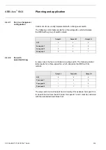
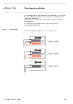
Control of a fan is usually implemented with a changeover switch.
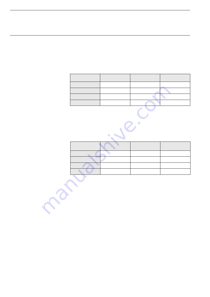
The following control table results for a three-stage fan, which simulates
the RM/S with a group of switch outputs:
Output L
Output M
Output N
OFF
0 0 0
Fan speed 1
1 0 0
Fan speed 2
0 1 0
Fan speed 3
0 0 1
4.4.2.2
Fan with
speed switching
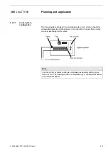
In some cases the fan is controlled via a step switch. The following control
table results for a three-speed fan, which simulates the RM/S with its
outputs:
Output L
Output M
Output N
OFF
0 0 0
Fan speed 1
1 0 0
Fan speed 2
1 1 0
Fan speed 3
1 1 1
The step switch cannot be switched on rapidly. If for example, fan speed 3 is
to be switched on from the OFF state, fan speeds 1 and 2 must be controlled
with the associated dwell times first.

