background image

ABB i-bus

®

 KNX 

Product overview 


12   9AKK107992A4580_EN Rev. A | SU/S 30.640.2 

3.5.3 

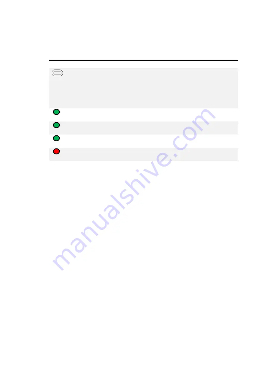
Operating and display elements 

Button/LED 

Description 

LED indicator 


Reset 

With reset, the overload display and the fault 

signal relay are reset, there is no reset of the KNX 

bus. 
If the fault has not been rectified before pressing 

the reset button, the fault is still present, the 

potential-free changeover contact and the LED 

remain in the fault position. 


AC Input 

Off: No mains voltage 
On: Mains voltage OK 


Battery 

Off: No battery connected or battery fault 
On: Battery OK 


U

N

 KNX 

Off: Overload/bus line short circuit 
On: Bus line OK 


I

N

 Overload 

Off: Bus line OK 
On: Overload/bus line short circuit 

Tab. 4: Operating and display elements 


Summary of Contents for i-bus KNX SU/S 30.640.2

Page 1: ... PRODUCT MANUAL ABB i bus KNX SU S 30 640 2 Uninterruptible KNX Power Supply 640 mA ...

Page 2: ......

Page 3: ...2 MDRC 10 3 5 1 Dimension drawing 10 3 5 2 Connection diagram 11 3 5 3 Operating and display elements 12 3 5 4 Technical data 13 4 Function 15 4 1 Device functions 15 4 2 Monitoring and fault messages 16 4 2 1 Bus line monitoring 16 4 2 2 Mains voltage monitoring 16 4 2 3 Battery voltage monitoring 16 4 2 4 Diagnostic table 17 5 Mounting and installation 19 5 1 Information about mounting 19 5 2 Mo...

Page 4: ... 2 Back up supply 37 12 3 Battery service life 38 13 Appendix 39 13 1 Scope of delivery 39 13 2 Accessories 39 13 2 1 Technical data of Cable Set Basic KS K 4 1 GHQ6301910R0001 39 13 2 2 Technical data of Cable Set Extension KS K 2 1 GHQ6301910R0011 39 13 2 3 Technical data of SAK2 GHV9240001V0010 40 13 2 4 Technical data of SAK7 GHV9240001V0011 40 13 2 5 Technical data of SAK12 GHV9240001V0012 40...

Page 5: ... agreed conditions shall be decisive ABB AG accepts no responsibility whatsoever for potential errors or possible lack of information in this document We reserve all rights to this document and the objects and illustrations contained therein Reproduction transfer to third parties or processing of the content including sections thereof is not permitted without the prior written consent of ABB AG Co...

Page 6: ...h risk hazards that will definitely result in death or serious injury unless avoided WARNING Indicates medium risk hazards that could result in death or serious injury unless avoided CAUTION Indicates low risk hazards that could result in slight or moderate injury unless avoided ATTENTION Indicates a risk of malfunctions or damage to property and equipment but with no risk to life and limb Example...

Page 7: ... data Operate the device only in a closed housing distribution board Mounting and installation must be carried out only by qualified electricians Disconnect the device from the supply of electrical power before mounting 2 2 Proper use The product must be installed centrally in an electrical distribution board The device is a modular installation device for quick installation in distribution boards...

Page 8: ......

Page 9: ...8 division units DU the device is designed for installation in distribution boards on a 35 mm mounting rail The connection to the ABB i bus KNX is established via a bus connecting terminal on the front After connecting the mains voltage the unit is ready for operation 3 2 Product name description Abbreviation Description S Power Supply U Uninterruptible S MDRC X 30 Bus voltage V X 640 Bus current ...

Page 10: ...iew 10 9AKK107992A4580_EN Rev A SU S 30 640 2 3 5 Uninterruptible KNX Power Supply 640 mA SU S 30 640 2 MDRC Fig 1 Device illustration SU S 30 640 2 3 5 1 Dimension drawing Fig 2 Dimension drawing 9PAA00000059996 2CDC072027F0017 ...

Page 11: ...l carriers 8 Code 650 mA and temperature sensor 2 LED without function 9 Battery connection 3 Reset button 10 Mains connection 4 KNX connection 11 Floating changeover contact 5 Cover cap 12 AC Input LED green 6 Temperature sensor connection 13 Battery LED green 7 150 mA and temperature sensor 14 Un KNX LED green 15 In Overload LED red 9AKK107992A4484 ...

Page 12: ... bus If the fault has not been rectified before pressing the reset button the fault is still present the potential free changeover contact and the LED remain in the fault position AC Input Off No mains voltage On Mains voltage OK Battery Off No battery connected or battery fault On Battery OK UN KNX Off Overload bus line short circuit On Bus line OK IN Overload Off Bus line OK On Overload bus line...

Page 13: ... Us 3 screw terminals Connection type battery connection Ubat incl temperature sensor 4 screw terminals Connection type changeover contact 3 screw terminals Connection type load circuit Screw terminal with universal head PZ 1 Pitch 6 35 mm Tightening torque screw terminals 0 6 Nm Conductor cross section fine stranded All screw terminals 0 75 2 5 mm Conductor cross section single core All screw ter...

Page 14: ...nge Operation 5 45 C Transport 25 70 C Storage 25 55 C Ambient conditions Humidity 95 Atmospheric pressure Atmosphere up to 2 000 m Design Modular installation device MDRC Modular installation device Design pro M Housing color Polycarbonate Makrolon FR6002 halogen free Dimensions Dimensions 90 140 63 5 mm H x W x D Mounting width in space units 8 modules 17 5 mm each Mounting depth 68 mm Mounting ...

Page 15: ... bus connecting terminal must be disconnected from the power supply Up to two 12 V lead gel accumulators can be connected to buffer the KNX system voltage in the event of mains voltage failures The batteries are charged via the SU S 30 640 2 A temperature sensor is used to control the charging voltage In the event of a mains voltage failure the SU S 30 640 2 is powered by the batteries ATTENTION T...

Page 16: ... for longer than 10 seconds the floating changeover contact switches to the fault position 4 2 2 Mains voltage monitoring In the event of a mains voltage failure the bus line is supplied from the connected accumulator No faults will occur in the system If the mains voltage fails the potential free changeover contact switches to the fault position and the AC Input LED extinguishes When the mains po...

Page 17: ...d mains power failure battery operation In the event of a short circuit eliminate the cause of the short circuit reduce the number of devices in the event of an overload switch on the mains voltage supply acknowledge the fault perform a reset Green Off Red Fault Overload or short circuit no battery battery error or battery discharged In the event of a short circuit eliminate the cause of the short...

Page 18: ......

Page 19: ...ard Disconnect all phases before working on the electrical connection 5 2 Mounting on DIN rail The device is fitted and removed without auxiliary tools Make sure the device is accessible for operation testing visual inspection maintenance and repair Fig 4 Mounting on DIN rail 1 Place the DIN rail holder on the upper edge of the DIN rail and push down 2 Push the lower part of the device toward the ...

Page 20: ...te Cable Sets KS K 4 1 and KS K 2 1 are not supplied with the device Order number for KS K 4 1 GHQ6301910R0001 Order number for KS K 2 1 GHQ6301910R0011 Cable Set KS K 4 1 includes a replaceable fuse and a temperature sensor for temperature controlled charging voltage adjustment Cable Set KS K 2 1 includes a replaceable fuse ATTENTION When connecting one or two batteries connected in parallel the ...

Page 21: ...t battery White Temp sensor Yellow Temp sensor Black Battery GND Red Battery 12 V KS K 2 1 2nd battery Black Battery GND Red Battery 12 V Tab 7 Connecting the KS K 4 1 and KS K 2 1 to the Power Supply SU S 30 640 X The maximum charging time of the Sealed Lead Acid Batteries is SAK7 16 h 1 x SAK7 or 32 h 2 x SAK7 parallel SAK12 28 h 1 x SAK12 or 56 h 2 x SAK12 parallel SAK17 39 h 1 x SAK17 or 78 h ...

Page 22: ...arging current adjustment the temperature sensor is integrated in the AM S 12 1 ATTENTION The temperature sensor must be connected in any case so that the battery is charged properly and does not overheat during charging Observe the following guidelines when using the battery module AM S 12 1 The battery module may only be connected to the uninterruptible EIB KNX power supply SU S 30 640 x The bat...

Page 23: ...KNX Mounting and installation SU S 30 640 2 9AKK107992A4580_EN Rev A 23 Connecting the AM S 12 1 to the Power Supply SU S 30 640 X Fig 6 Connecting the AM S 12 1 to the Power Supply SU S 30 640 X 9AKK107992A4477 ...

Page 24: ......

Page 25: ... is performed every 15 minutes In the most unfavorable case it can take up to 15 minutes after connection before a possible battery fault is indicated or reset Likewise it can take up to 15 minutes for the Battery LED to illuminate after the cause for a fault is corrected Pressing the Reset button can trigger a manual battery test If an overload fault is logged but is no longer active this fault i...

Page 26: ......

Page 27: ...ABB i bus KNX Parameters SU S 30 640 2 9AKK107992A4580_EN Rev A 27 7 Parameters This section is not relevant for this device ...

Page 28: ......

Page 29: ...ABB i bus KNX Group objects SU S 30 640 2 9AKK107992A4580_EN Rev A 29 8 Group objects This section is not relevant for this device ...

Page 30: ......

Page 31: ...esetting the saved overload indication Press the Reset button to perform a reset The overload indication and the fault signaling relay will be reset The bus connection terminal must be disconnected from the Power Supply to de energize the bus line For more information see chapter 4 3 ...

Page 32: ......

Page 33: ...aintenance The device is maintenance free Any damage due to transport or storage for example must not be repaired 10 2 Cleaning Disconnect the device from mains voltage before cleaning Dirty devices can be cleaned with a dry cloth or a cloth slightly moistened with soapy water Never use corrosive agents or solutions ...

Page 34: ......

Page 35: ...esources that can be recycled Therefore please take the device to a suitable recycling center All packaging materials and devices are provided with markings and test seals for proper disposal Always dispose of packaging material and electrical devices or their components at collection points or disposal companies authorized for this purpose The products comply with the statutory requirements parti...

Page 36: ......

Page 37: ... unit the SAK 7 SAK 12 and SAK 17 lead gel accumulators can be installed in a separate distribution board When the uninterruptible KNX power supply SU S 30 640 2 KNX bus 640mA is used at full capacity the lead gel accumulators buffer the KNX system voltage for the following mains voltage failure bridging times Battery module 12 V DC MDRC AM S 12 1 Battery capacity 1 Ah Mains power failure backup t...

Page 38: ...he maximum mains voltage failure bridging time The following diagrams show the backup times depending on the number of powered KNX devices The top diagram shows the backup times at a larger scale backup for up to 50 hours The bottom diagram shows the backup times at a smaller scale backup times up to 20 hours Fig 8 KNX backup times up to 50 hours Fig 9 KNX backup times up to 20 hours 9AKK107992A44...

Page 39: ...nnection For connection to SU S 30 640 X wire end ferrules For connection to the battery Faston sockets and pole shoes Temperature sensor Wire end ferrules Fuse Class User replaceable fuse with in line fuse holder with bayonet lock Type 5 x 20 mm slow blow T 6 3 H 250 V breaking capacity 1 500 A Weight 0 1 kg Tab 8 Technical data of KS K 4 1 13 2 2 Technical data of Cable Set Extension KS K 2 1 GH...

Page 40: ...13 2 4 Technical data of SAK7 GHV9240001V0011 Supply Rated voltage 12 V DC Battery capacity 7 Ah Temperature range Operation 20 50 C Transport 20 50 C Storage 20 20 C Dimensions 94 151 65 mm H x W x D Weight 2 6 kg Service life 5 years Tab 11 Technical data of SAK7 13 2 5 Technical data of SAK12 GHV9240001V0012 Supply Rated voltage 12 V DC Battery capacity 12 Ah Temperature range Operation 20 50 C...

Page 41: ...bus load the mains power failure backup time decreases as the battery module ages Safety Temperature sensor Integrated Fuse Self healing integrated Connections Power Supply 2 screw terminals Temperature sensor 2 screw terminals Connection cross section Fine stranded 0 2 2 5 mm2 Solid 0 2 4 mm Degree of protection IP 20 EN 60 529 Temperature range Operation 5 45 C Transport 25 50 C Storage 25 20 C ...

Page 42: ...ABB i bus KNX Appendix 42 9AKK107992A4580_EN Rev A SU S 30 640 2 13 3 Notes ...

Page 43: ...ABB i bus KNX Appendix SU S 30 640 2 9AKK107992A4580_EN Rev A 43 ...

Page 44: ...f this document at any time without advance notice The agreed properties are definitive for any orders placed ABB AG does not accept any responsibility whatsoever for potential errors or possible lack of information in this document We reserve all rights in this document and in the subject matter and illustrations contained therein Reproduction transfer to third parties or processing of the conten...

Reviews: