ABB i-bus® KNX
PLANNING AND APPLICATION
Analog (proportional) valve drives
The valve positions between 0 % and 100 % are adopted using a motor in analog (proportional) valve
drives. Analog (proportional) valve drives are controlled via a 0-10 V signal. The power for the valve drive
is normally supplied via 230 V AC or 24 V AC/DC.
Due to aging processes or mechanical inaccuracies in the valve, the valve may not shut completely de-
spite the control value 0 %. To prevent this situation arising, there are valve drives that can be activated
via a 0-10 V signal or a 2-10 V signal → parameter Voltage range valve control value. With this activation,
the output signal is restricted to the corresponding voltage range. To make sure that the valve is always
closed completely, the 0 V signal is nevertheless output for the control value 0 %. If the control value is
greater than 0 %, the lower limit (1 V or 2 V) is used directly for the activation.
Activation via 1-10 V signal:
• Control value 0 % = 0 V
• Control value 1 % = 1 V
• Control value 100 % = 10 V
Activation via 2-10 V signal:
• Control value 0 % = 0 V
• Control value 1 % = 2 V
• Control value 100 % = 10 V
9AKK107991A9760
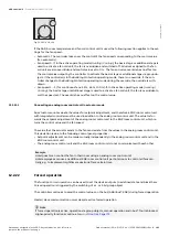
Fig. 32: Control by valve control values
12.2.18
Telegram rate limit
The bus load generated by the device can be limited using the telegram rate limit. This limit relates to all
telegrams sent by the device.
Product manual | EN-US | VC/S 4.x.1 | 2CDC508220D0211 Rev. B
189
Note about navigation in the PDF: Key combination 'Alt + left arrow'
jumps to the previous view/page


