QUICK START GUIDE
Page 10
© 2021 ABB. All rights reserved.
Step 9
-
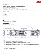
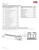
Connect Controller Signals and Alarms
Connect per site engineering instructions.
See information: signals Connections for details.
Independent connections are on the front of the charger controller, behind a cover.
Route cables thru DC Cable Entry Panel, behind left front mounting rail, through wire port behind the left mounting
ear of the controller.
Leave
12”
slack in cables to allow slide controller to be removed in the event replacement is needed.
Secure with wire ties as desired.
Alarm Wires
TB1, TB2, TB3, TB4, & TB6 Alarms –
detachable blocks –
Wire to site alarms and signals. See Information: Signal
Connections.
Strip –
0.35”
(9mm), Torque –
2
in
-
lb. (0.25Nm)
LAN
LAN Ethernet LAN or Local PC connection
Temperature Probes
1
-
Wire Thermal Probes –
Optional
Step 10 –
Installing Rectifiers and Converters
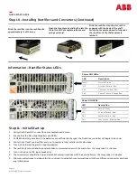
Caution: The rectifier/converter latch is not a carrying handle.
1.
Slide the rectifier/converter into the rectifier/converter slot approximately ¾ of the way.
2.
Open the faceplate by sliding the latch to the left until the faceplate releases and swings outward.
3.
Slide the rectifier/converter into the slot until it engages with the back of the shelf. Swing the faceplate closed to fully
seat the rectifier/converter. Verify the faceplate is latched.
4.
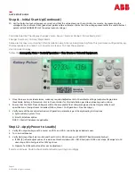
Correct insertion of the rectifier/converter will automatically add the unit to the controllers
’
inventory of units.
To remove a rectifier:
1.
Open latch fully to release and remove.
2.
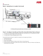
Enter Inventory section of controller and remove hardware to clear alarm.


