QUICK START GUIDE
Page 11
© 2021 ABB. All rights reserved.
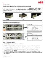
Step 10 –
Installing Rectifiers and Converters (Continued)
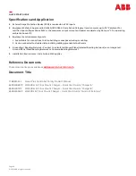
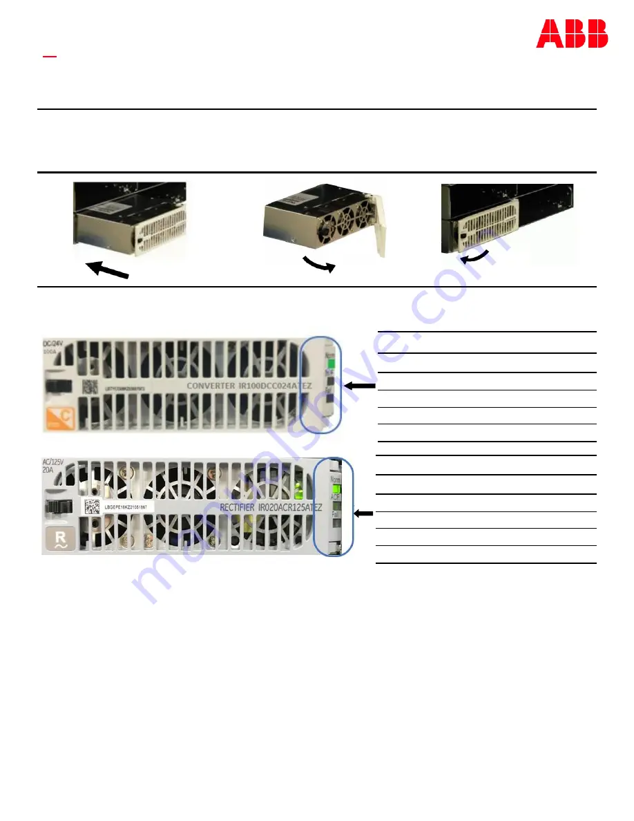
Slide the rectifier into the rectifier slot
approximately ¾ of the way
Open the faceplate by sliding the latch to
the left until the faceplate releases and
swings outward.
Slide the rectifier into the slot until it
engages with the back of the shelf.
Swing the faceplate closed to fully seat
the rectifier. Verify the faceplate is
latched.
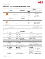
Power Unit LEDs
LED
Description
Norm
Normal
-
Green
ACF
AC input Failure
-
Red
Fail
Rectifier Failure
-
Red
Fail
Com. Failure
-
Blinking Red
Information –
Rectifier Status LEDs
Power Unit LEDs
LED
Description
Norm
Normal
-
Green
IN F
DC input Failure
-
Red
Fail
Converter Failure
-
Red
Fail
Comm. Failure
-
Blinking Red
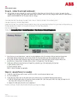
Step 11
-
Initial Start Up
1.
Verity that AC and DC connections are complete and secure.
2.
Ensure that the DC output breakers are OPEN.
3.
CLOSE the battery breakers if the batteries are sufficiently charged, the Fire & Gas controller will begin to boot up.
4.
Verity that at least one Rectifier and one Converter is fully installed in Step 8 above.
5.
Turn on Fire & Gas Charger AC input breaker(s).
6.
The rectifier(s) should start up and establish communications with the controller –
that may take 1
-
2 minutes.
7.
Turn on the Control DC input breaker(s).
8.
The converter(s) should start up and establish communications with their controller(s) –
that may take 1
-
2 minutes.
9.
Allow several minutes to elapese for the controller to establish communications with the rectifier and converter and clear
any initial alarms.


