QUICK START GUIDE
Page 7
© 2021 ABB. All rights reserved.
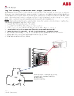
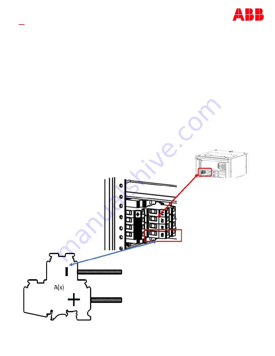
Step 6 Connecting 125Vdc Power from Charger Cabinets A and B
The 24VDC Control charger is equipped with a Converter A and a Converter B system. Each converter is comprised
of two converter shelves managed by its own controller. The system is configured to accept 125Vdc inputs from
two charger sources; Charger A and Charger B. Chargers A and B provide input power via A1, A2 and B1, B2 terminal
blocks located behind the removable panel directly below the upper 70Aac Input AC Panel. Charger A provides the
power to A1(+/
-
) and A2(+/
-
) while Charger B provides the power to B1(+/
-
) and B2(+/
-
).
Caution: When routing cables through cabinet chambers, ensure that wires do not contact sharp or rough surfaces
that may damage insulation and cause a short circuit.
1.
Remove AC Panel front cover (4 screws—
5/16
socket).
2.
Route cables from the 125Vdc cabinets through the Top Access Panel.
3.
Punch appropriate size holes in the DC Cable Entry Panel for the 125Vdc DC/DC converter inputs.
4.
Punch additional holes for future use and install hole covers in unused holes. (Recommended)
5.
Route all cables carefully through cabinet. Use cable ties and integrated cable management features.
6.
Strip ends of A1, A2, B1 and B2 (+ /
-
) wires each to
7/16”
(11mm). The application of a Ferrule is recommended.
7.
Insert positive wires to lower positions and negative wires to upper positions.
8.
Torque each connection to 20 in
-
lbs. (2.6 Nm).
Cables exit towards the cabinet read and route up
towards the cable access panel note Polarity .
NEGATIVE ON TOP
POSSITIVE ON BOTTOM


