QUICK START GUIDE
Page 9
© 2021 ABB. All rights reserved.
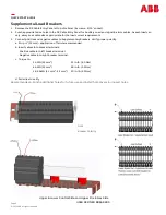
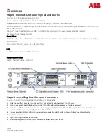
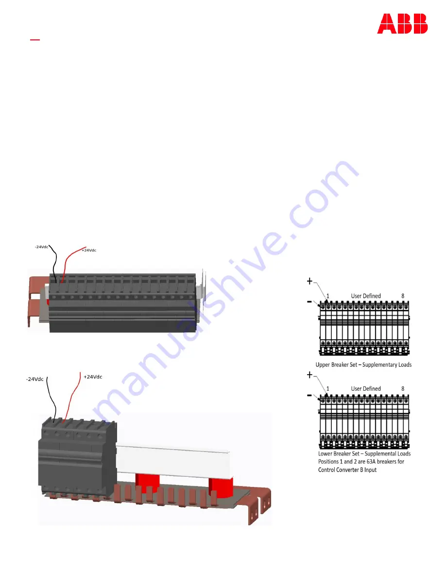
Supplemental Load Breakers
1.
Remove the DC Cable Entry Panel at top of cabinet (4 screws
-
5/16”
socket).
2.
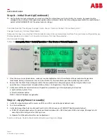
Punch appropriate size holes in the DC Cable Entry Panel for Ancillary Load and signal & alarm cables. As each load can
vary, always use cable sizes appropriate for the load current requirements.
3.
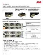
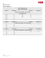
Connect positive and negative cables to Supplementary Breakers. Verify proper polarity.
a.
Strip ½
” (12
mm) –
application of ferrule recommended.
b.
Insert cables into breaker terminals:
Positive cable into left breaker terminal.
Negative cable into right breaker terminal.
c.
Torque to:
d.
Pull wires to verify.
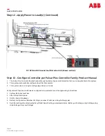
Recommended—Punch additional holes for future use and install hole covers in unused holes.
2 AWG (35 mm²)
35 in
-
lb. (4.0 Nm)
4 AWG (23 mm²)
28 in
-
lb. (3.2 Nm)
18
-
6 AWG (1.1 mm²
-
4.2 mm²)
20 in
-
lb. (2.3 Nm)
Note:
Breaker Polarity
Upper & Lower Control Side and Upper Fire & Gas Side
USER DEFINED BREAKERS


