Note
Action
See
Lift the robot.
5
2 pcs, D6x20, ISO 2338 - 6m6x20
- A1
Fit two pins to the holes in the base.
6
Make sure the robot base is cor-
rectly fitted onto the pins.
Guide the robot gently, using the attachment
screws while lowering it into its mounting position.
7
Screws: M12x25 (robot installation
directly on foundation), 4 pcs,
quality 8.8
Fit the securing screws and washers in the attach-
ment holes of the base.
8
Washers: 24 x 13 x 2.5, steel hard-
ness class 200HV
Tightening torque: 50 Nm±5 Nm
Tighten the bolts in a crosswise pattern to ensure
that the base is not distorted.
9
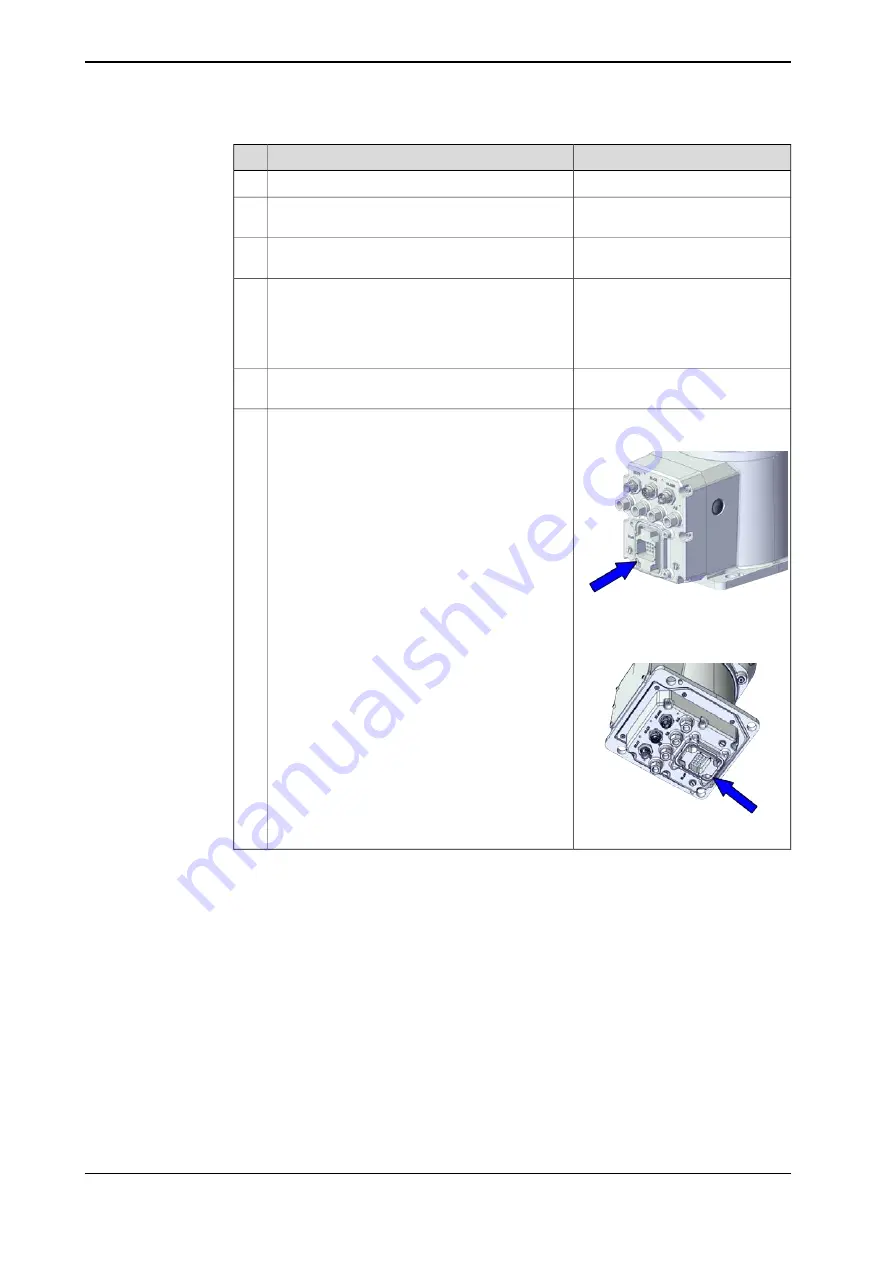
Robots with manipulator cables
routed from the rear of the base:
xx1900002163
For robots with protection class IP67 (option
3350-670)
For robots with protection type Clean Room
(option 3351-4)
Fit the O-ring 3HAB3772-19 to the main power
connector on the robot base.
10
Robots with manipulator cables
routed from below (3309-1):
xx1900002164
Continues on next page
64
Product manual - IRB 1100
3HAC064992-001 Revision: L
© Copyright 2019-2022 ABB. All rights reserved.
3 Installation and commissioning
3.3.2 Orienting and securing the robot
Continued
Summary of Contents for IRB 1100
Page 1: ...ROBOTICS Product manual IRB 1100 ...
Page 8: ...This page is intentionally left blank ...
Page 16: ...This page is intentionally left blank ...
Page 38: ...This page is intentionally left blank ...
Page 50: ...This page is intentionally left blank ...
Page 738: ...This page is intentionally left blank ...
Page 760: ...This page is intentionally left blank ...
Page 764: ......
Page 765: ......


