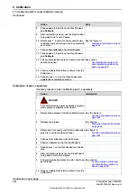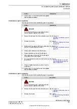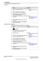
Calibration of axes 5 and 6 using the calibration tool
Use this procedure when calibrating axes 5 and 6 separately.
Information
Action
DANGER
Turn off all electric power, hydraulic and pneu-
matic pressure supplies to the robot!
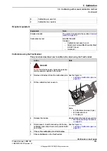
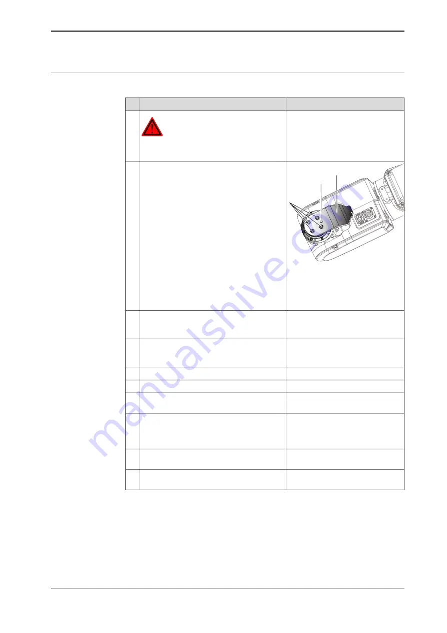
1
B
C
A
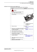
xx1000000005
Fit the
calibration tool
on the wrist with its
at-
tachment screws
.
2
Parts:
•
A: Attachment screws (4 pcs)
•
B: Calibration tool
•
C: Guide pin
See section
•
Manually releasing the brakes
on page 66
Release the brakes.
3
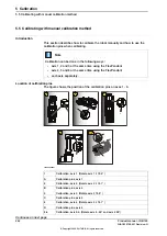
See figure 5-6 in:
•
Location of calibration pins on
page 242
Rotate axes 5 and 6 manually until the
calibra-
tion pin
on the wrist and the
fork
of the tool are
in contact with each other.
4
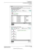
Choose fine calibration from Calib menu.
5
Choose Calibrate on the the FlexPendant.
6
After calibration is done use the FlexPendant
to jog each axis to zero degree.
7
See section
•
Synchronization marks and
synchronization position for
axes on page 228
The
synchronisation marks
on axes 5 and 6
shall now be matched.
8
Choose
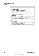
Update Revolution counters
from the
Calib menu
.
9
Choose
Axis 5 to 6
on the FlexPendant and
update the revoultion counters
.
10
Product manual - IRB 120
247
3HAC035728-001 Revision: N
© Copyright 2009-2017 ABB. All rights reserved.
5 Calibration
5.5 Calibrating with manual calibration method
Continued
Summary of Contents for IRB 120
Page 1: ...ROBOTICS Product manual IRB 120 ...
Page 8: ...This page is intentionally left blank ...
Page 90: ...This page is intentionally left blank ...
Page 114: ...This page is intentionally left blank ...
Page 224: ...This page is intentionally left blank ...
Page 250: ...This page is intentionally left blank ...
Page 254: ...This page is intentionally left blank ...
Page 264: ...This page is intentionally left blank ...
Page 270: ......
Page 271: ......

