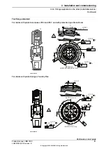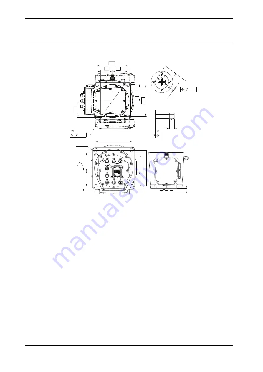
Hole configuration, base
This illustration shows the hole configuration used when securing the robot.
190
190
100
10
H7
+
0.015
0
73
100
73
A
B
B
Detail A
Section B
0.08
10
H7
+
0.015
0
0.5
0.5
0.08
18.5
22
0.2
R101,5
118
190
190
189
80
170
96
21
xx1900001337
70
Product manual - IRB 1300
3HAC070390-001 Revision: G
© Copyright 2020-2022 ABB. All rights reserved.
3 Installation and commissioning
3.3.3 Orienting and securing the robot
Continued
Summary of Contents for IRB 1300
Page 1: ...ROBOTICS Product manual IRB 1300 ...
Page 8: ...This page is intentionally left blank ...
Page 36: ...This page is intentionally left blank ...
Page 100: ...This page is intentionally left blank ...
Page 746: ...This page is intentionally left blank ...
Page 762: ...This page is intentionally left blank ...
Page 764: ...This page is intentionally left blank ...
Page 768: ......
Page 769: ......


